Hex Screw
M3x14 (×1)
(7-224)
Main Rotor Shaft
Clamp (×1)
(7-031)
Ball Joint Screw
M3xΦ6x6.7 (×4)
(7-145)
M3 Nyloc Nut (×4)
(7-163)
OMP Plastic
Servo Arm (×4)
(7-049J)
Hex Screw
M3x8 (×4)
(7-127)
Swashplate Servo (×3)
(7-198)
Tail Rotor Servo (×1)
(7-199)
Hex Screw
M2.5x12 (×8)
(7-124)
Servo Alignment
Plate (×4)
(7-038)
Hex Screw
M2.5x8 (×4)
(7-123)
Servo Alignment
Nut (×2)
(7-037)
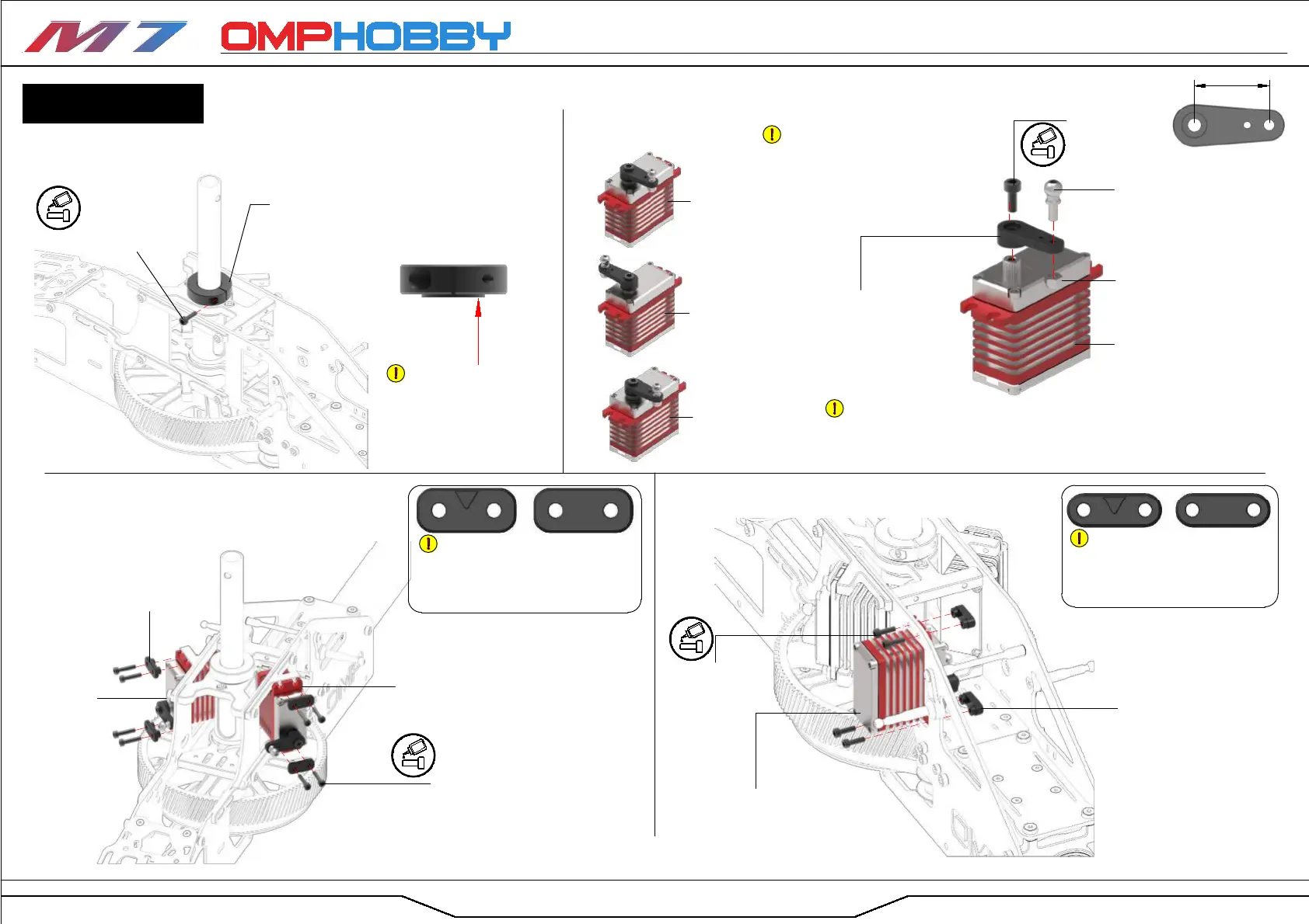
01 Main Rotor Shaft Clamp Installation
02 Servo Assembly
03 Front Servo Installation 04 Rear Servo Installation
If using OMP plastic servo arms, please use M3xΦ6x6.7 ball joint
screws with nyloc nuts.
If you are using metal servo arms, please use M3xΦ6x4.6 ball joint
screws without nyloc nuts.
Servo Installation
Your M7 comes with two sets of
servo alignment plates, featuring
4mm studs (marked with a triangle)
and 5mm studs. Choose the ones
appropriate for your servo.
Your M7 comes with two sets
of servo alignment plates, featuring
4mm studs (marked with a triangle)
and 5mm studs. Choose the ones
appropriate for your servo.
Page
The flange of the clamp
ring should face downwards
and contact the bearing.
Ensure there is no vertical
play in the main shaft after
installation.
18mm
Right Servo
Ch3 (×1)
Left Servo
Ch2 (×1)
After finding the neutral position
with the help of your flight controller,
assemble three servos with two different
arm orientations. The angle of the arm
relative to the servo body should be 90° .
Rear Servo
Ch1 (×1)
Right Servo
Ch3 (×1)
Left Servo
Ch2 (×1)
Rear Servo
Ch1 (×1)
Glue
Glue
Glue
Glue
BAG 15