Electronic Fluxmeter EF 14
3 Operation
The basics for operation of the EF 14 fluxmeter are described here. A description of all the
elements of display in measuring operation (standard display) is to be found in chapter 3.1. An
overview of the keys and their functions is given in chapter 3.2.
3.1 Display
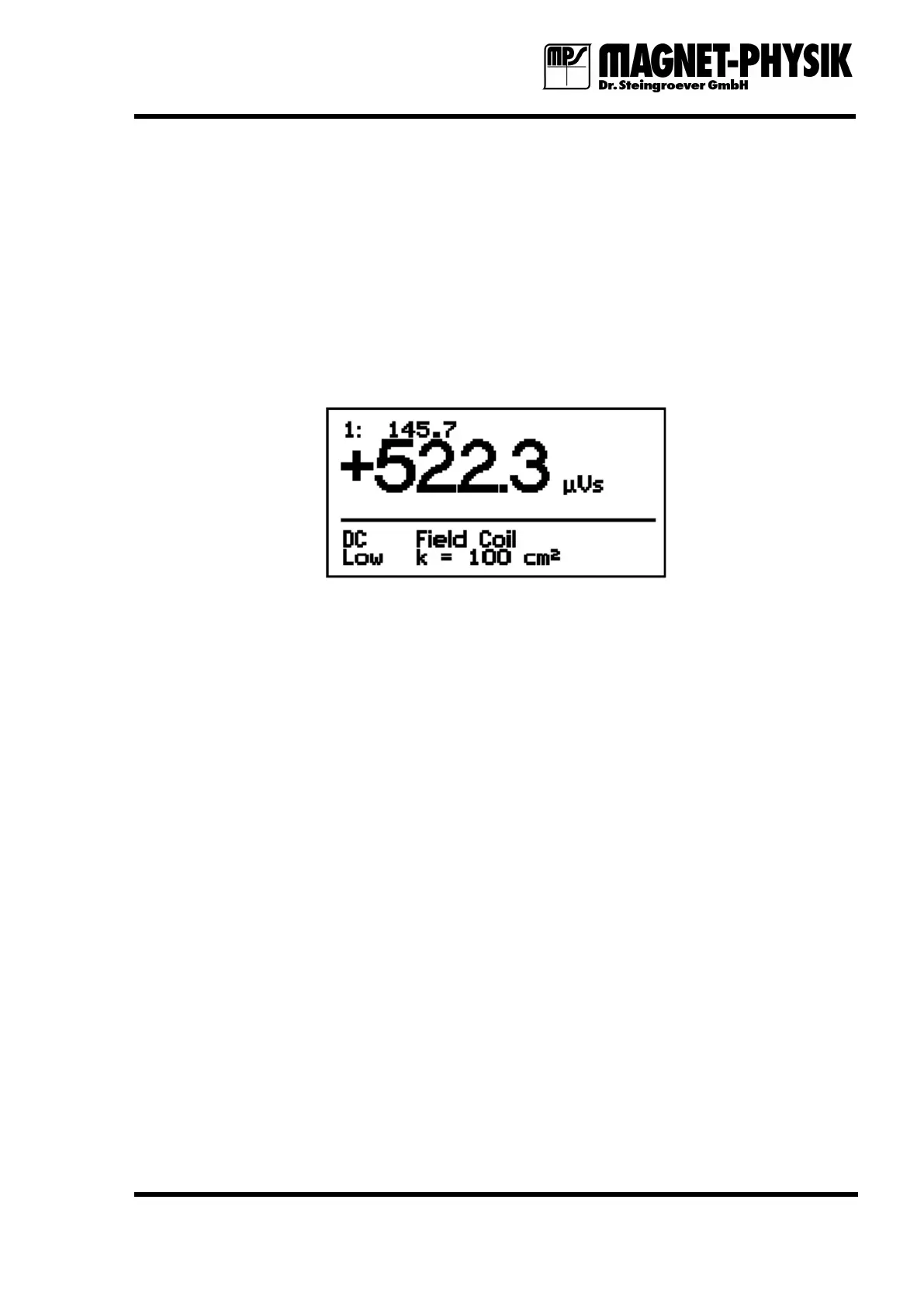
Fig. 3.1.1: Display in measuring operation
In measuring operation the actually measured value is shown in the center of the display in
large numbers. It is the numerical value with a maximum of four digits and the unit.
The two bottom lines provide various information:
1. Measuring mode: AC or DC
2. Limit state: Low, OK, High. Therefore the Limit function must be switched on.
3. Coil type: The type of the connected measuring coil, Field Coil in the example.
4. Coil constant: Constant of the connected measuring coil, k = 100 cm² in the example.
If the Var. function is switched on, this is shown instead of the coil constant.
Remote mode: If the EF 14 is controlled remotely via the serial interface and the keypad is
locked, this is assigned by an R in the upper right corner of the display.
If the Max./Min. function is switched on, the values measured with this function are shown in
the line below the main measured vale.
If the Peak function is switched on, the largest peak value is shown, independently of its sign,
in the center of the display in large numbers. Below this, the largest value with opposite sign is
shown.
Values that are stored in the data memory are shown in the upper left corner of the display.
The unit behind the actual measured value is valid for all displayed values.