5 Programming
MAGNETEK HPV1000 AC Elevator Drive Technical Manual 25
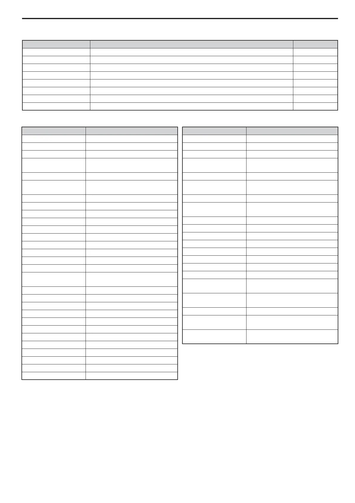
Table 11 C4 Analog Outputs
Table 12 Analog Output Choices
C4 Parameter Name Description
Default
Analog FM Select Terminal FM Monitor Selection Output Speed
Analog FM Level Sets the required working range of analog output FM -10 ~ +10VDC
Analog FM Gain Sets the signal level at terminal FM that is equal to 100% of the selected monitor value. 100.0
Analog FM Bias Sets the bias value added to the terminal FM output signal. 0.0
Analog AM Select Terminal AM Monitor Selection Output Current
Analog AM Level Sets the required working range of analog output AM -10 ~ +10VDC
Analog AM Gain Sets the signal level at terminal AM that is equal to 100% of the selected monitor value. 50.0
Analog AM Bias Sets the bias value added to the terminal AM output signal. 0.0
C4 Choice Description
AI Opt Ch1 Level AI Opt Ch1 Level
AI Opt Ch2 Level AI Opt Ch2 Level
AI Opt Ch3 Level AI Opt Ch3 Level
ASR Out w/o Fil
Yaskawa Speed Regulator output
(without filter)
Car Accel Rate
<4> Car Acceleration Rate
dAxis CtrlOutp
<2>, <3>, <4>
d-Axis Current Controller Output
DC Bus Voltage DC Bus Voltage
Distance-to-go <4> Remaining Distance
Encoder Counts Encoder Counts
Encoder Speed Encoder Speed
Heatsink Temp Heatsink Temperature
InertiaComp Outp
<3>, <4> Inertia Compensation Output
MaxCurrent@Acc Max. Current during Acceleration
MaxCurrent@Dec Max. Current during Deceleration
MaxCurrent@Level Max. Current during Leveling Speed
MaxCurrent@Run Max. Current during Constant Speed
Mot EXC Current
<2>, <3>, <4>
Motor Excitation Current (Id)
Mot SEC Current Motor Secondary Current (Iq)
Mot Overload Lvl Motor Overload Estimate (oL1)
Not Used Used to disable the outputs
Offset Frequency Output Frequency
Output Current Output Current
Output kWatts Output Power in kW
Output Speed Output Speed
Output Voltage Output Voltage
PID Diff Fdbk PID Regulator Difference
PID Feedback 1 PID Regulator Feedback 1
PID Feedback 2 PID Regulator Feedback 2
PID Input PID Input
PID Output PID Output
PID Setpoint PID Setpoint
PosLck Dev Count
<3>, <4> Position Lock Deviation Count
qAxis I CtrlOutp
<2>, <3>, <4>
q-Axis Current Controller Output
Ref Speed 2 Reference Speed 2
Rescue SpdLimLvl
Speed Reference limit at Rescue
Operation
Spd Ctrl Input
<3>, <4> Speed Control Loop Input
Spd Ctrl Output
<3>, <4>
Speed Control Loop Output
SpdFbkCmp Output
<4> Speed Feedback Compensation Output
Speed Command Speed Command
Speed Feedback Speed Feedback
Speed Reference Speed Reference
Term A1 Level Terminal A1 Input Voltage
Term A2 Level Terminal A2 Input Voltage
Term A3 Level Terminal A3 Input Voltage
Term RP Inp Freq Terminal RP Input Frequency
Torque Comp
<2>, <3>, <4>
Torque Compensation
Torque Reference
<2>, <3>, <4>
Torque Reference
Up/Dn 2 Bias Val Up/Dn Bias Value
Voltage Ref (Vd)
<2>, <3>, <4>
Output Voltage Reference (Vd)
Voltage Ref (Vq)
<2>, <3>, <4>
Output Voltage Reference (Vq)
<2> Parameter accessible in Open Loop Vector control mode
<3> Parameter accessible in Closed Loop Vector control mode
<4> Parameter accessible in PM Closed Loop Vector control mode
<5> Default is dependent on drive model number
C4 Choice Description