Flex 8EX / 12EX EU System Instruction Manual
March 2018
Page 54 of 66
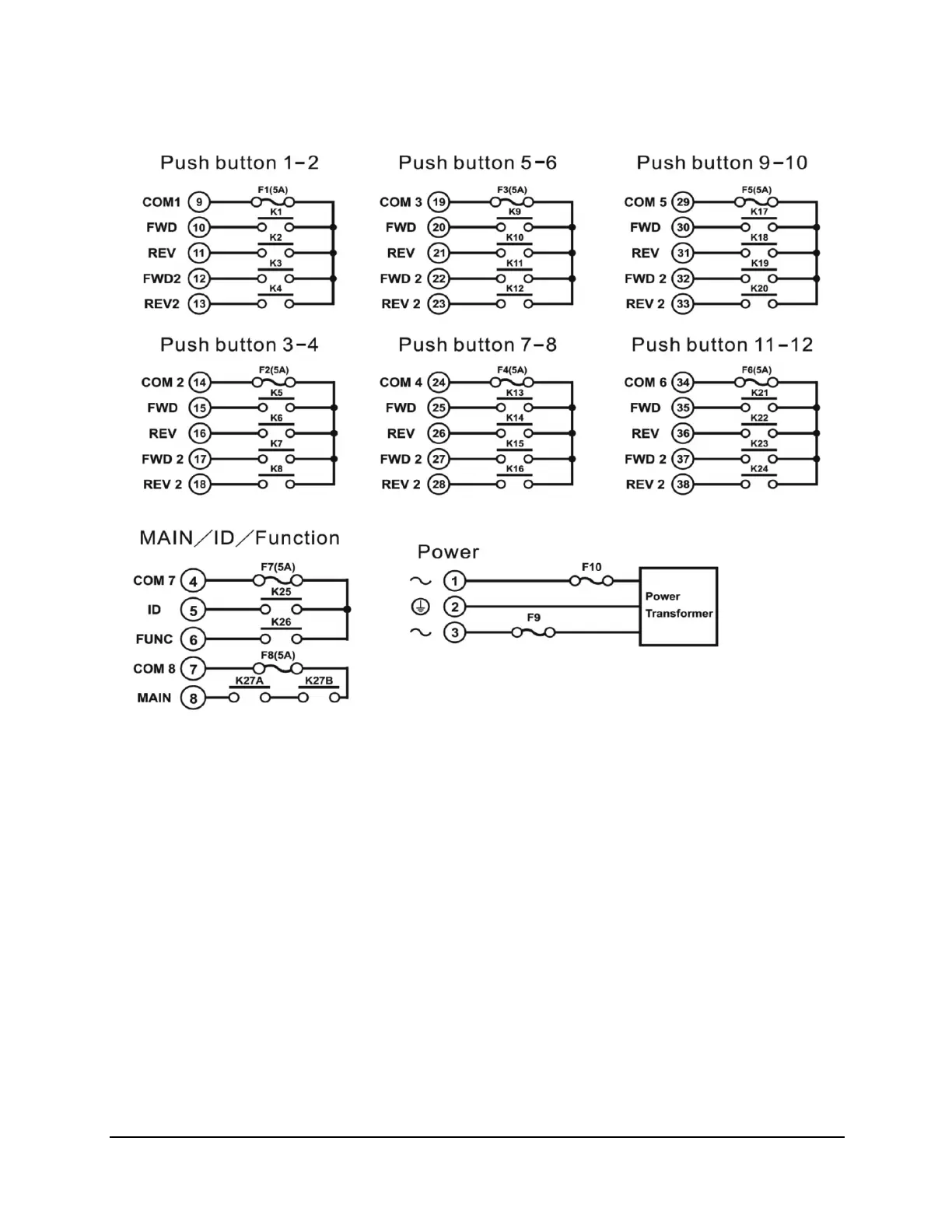
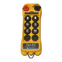
6.1.2 Flex 12EX
• For Flex A/B Systems, A connects to wire #26 (Flex 8EX) and wire #36 (Flex 12EX) and B
connects to wire #28 (Flex 8EX) and wire #38 (Flex 12EX).
• For 3-relay (shared 2nd speed) and 4-relay (separate 2nd speed) configuration, see Section
4.2.2.1 on page 41.
• For 4-relay closed/closed and 4-relay opened/closed configuration, see Section 4.2.2.2 on
page 41.
• For different voltage settings, see Section 4.2.7 on page 51.
• For F9 and F10 power fuse ratings, see Section 4.2.7 on page 51.
• For 12 - 24VDC power supply, wire #1 corresponds to the negative charge (-) and wire #3
corresponds to the positive charge (+). Wire #2 is for GROUND.
• Wire #6 is for “Normal Close” and wire #8 is for “Normal Open” MAIN output.
• Due to the possibility of voltage spikes on the contactors, suppressors are required on contactors
being driven by Flex relays.