Engineered XLTX Transmitter Instruction Manual
December 2016
Page 27 of 49
NOTE: The distance between the transmitter and receiver should be 1-2 feet for best results.
NOTE: The changes to the transmitter’s channel configuration and access code will not be saved
until the operator selects the Exit with Save option to exit the Setup Mode.
If the receiver is not in range, the scan will time out and the graphic user interface will display
“Failed”. The operator can reposition the transmitter and reattempt to establish the IR link with the
receiver by toggling the Start position on the OFF-ON-Start toggle multiple times.
NOTE: The access code and channel will not be updated to match the desired receiver until
“Success” is displayed. Once “Success” is displayed, subsequent “Failed” messages will not
overwrite the access code and channel obtained in the successful IR link until a new successful
IR link is made.
The IR configuration function will only update channel and access code information if the receiver
and transmitter are programmed at the factory with the same project identification number. If the
receiver/transmitter pairing is not programmed with the same project identification number, the
graphic user interface will display “Err Project ID” when an IR link is attempted. The IR link will not
be successful and the access code and channel information in the transmitter will not be
changed.
If the receiver and transmitter IR pair is not operating in the same frequency band when an IR link
is attempted, the graphic user interface will display “Err RF Freq”. The IR link will not be
successful and the access code and channel information in the transmitter will not be changed.
4.2.2.9 RCP IR Configuration
The RCP IR Configuration feature (supported in common code version 6.2 and greater) allows
the transmitter configuration to be read and written through the IR Adapter port. Contact customer
service to determine if your transmitter is compatible. You will also need to have an IR Adapter
available to configure the device.
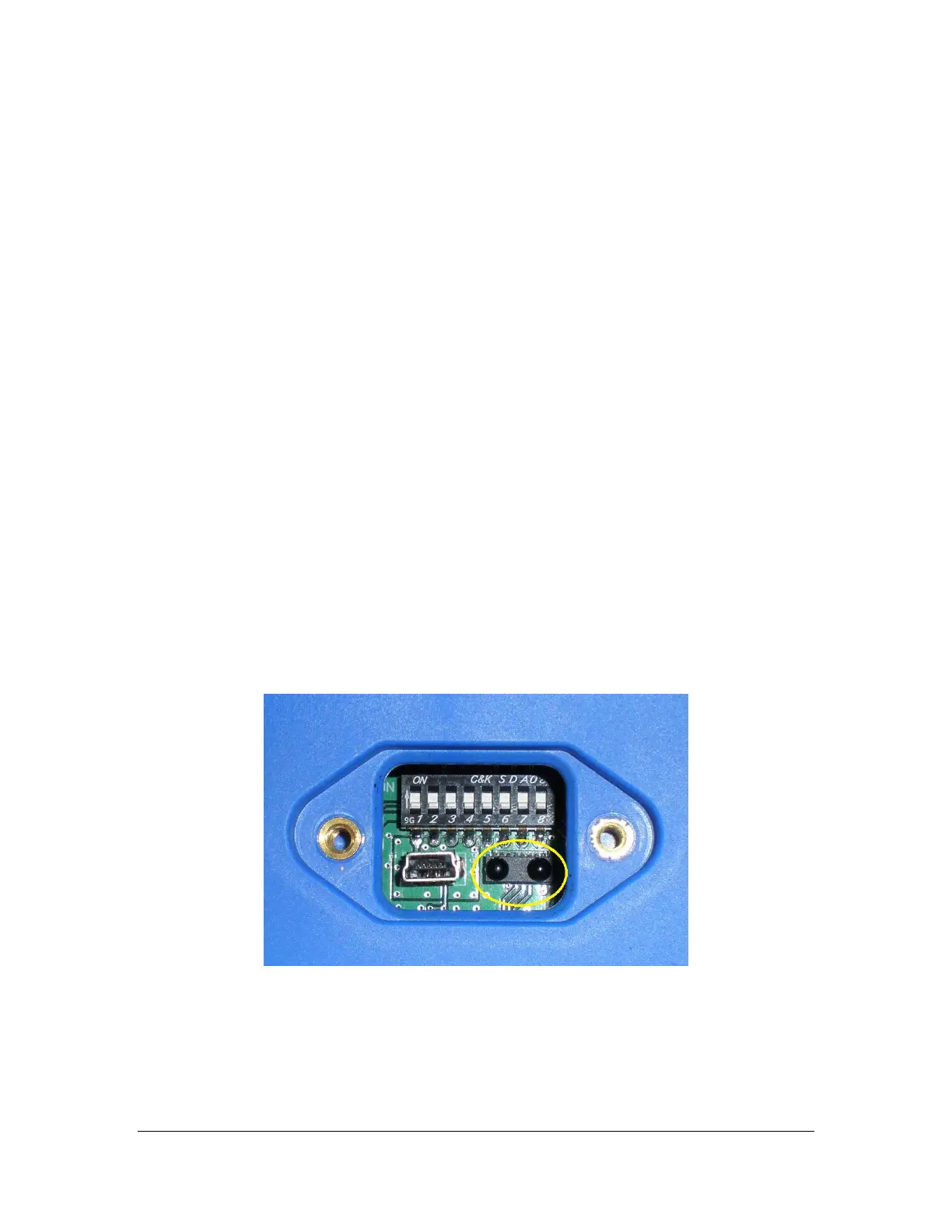
Figure 14: XLTX IR Window and LEDs
After selecting this option, point the IR Adapter at the IR window located on the bottom of the
transmitter (as seen in Figure 14Error! Reference source not found.).
 Loading...