5-How to Use the Tester
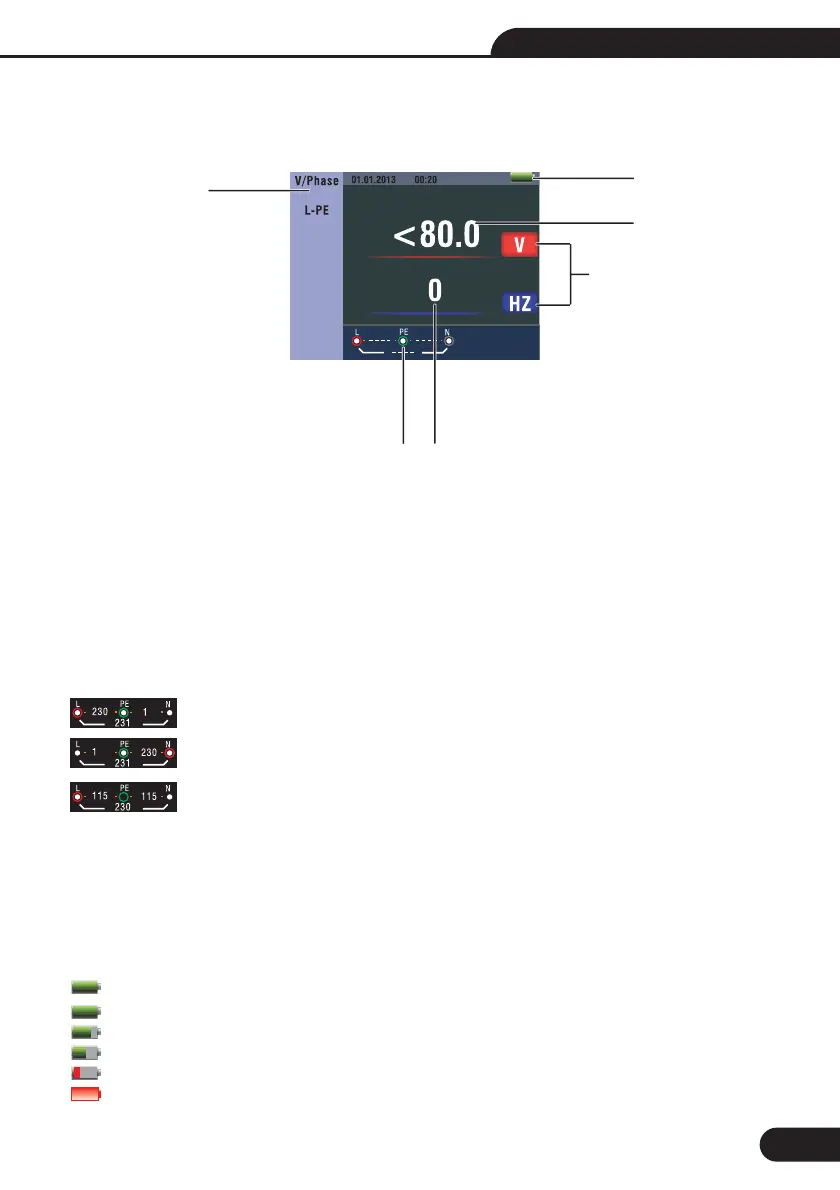
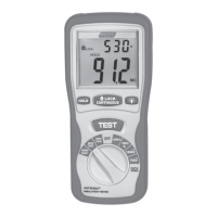
5.1-Important Symbols and Messages during the measurement
Description
Battery status
Displayed measured value
The measurement unit of the measured value
The indication of the correct input terminal connection
Displayed menu
5.1.1-Displayed icons (symbols) and messages in VOLTAGE function
:Indicates the correct input terminal connectivity . The user should connect the test leads
to the appropriate terminals.
:Indicates L connection is connected on the N input terminal and vice-versa
:Indicates no connection on the PE input terminal
If the wiring condition is other than normal, the Tester is limited on its measurements that can be performed.
• Will not detect two hot wires in a circuit.
• Will not detect a combination of defects.
• Will not detect reversal of grounded and grounding conductors.
:Indicates the battery status.
:100%
:80%
:50%
:20%
:Low Battery
1-
2-
3-
4-
5-
Notes:
5.1
5.1
5.1
5.1
5.1
5.1
5
1
3
2
24
Figure 1 Screen
13
Multifunction Tester User Manual