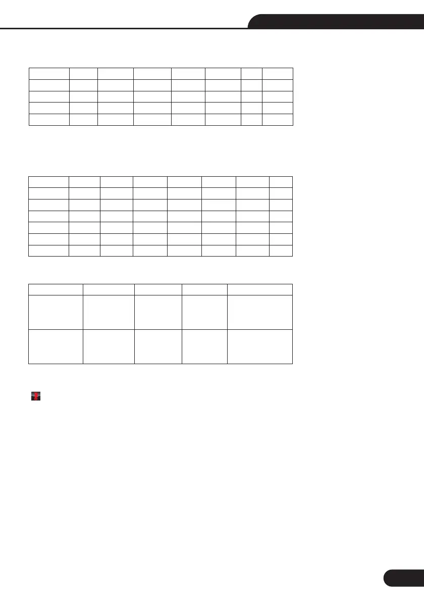
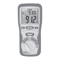
Possible setup ratios depending on the RCD Trip Current
Maximum measurement Trip Time of the RCD (Complying to BS 61008 and 61009)
IΔN: Trip-Out Current
tΔ: Trip-Out Time
: Indicates that the thermal protection device has operated and therefore cannot make any measurements.
Instrument must be allowed to cool for a period before tests can continue.
X
X1/2
X1
X2
X5
AUTO
RAMP
10mA
O
O
O
O
O
O
30mA
O
O
O
O
O
O
100mA
O
O
O
O
O
O
300mA
O
O
O
X
X
O
500mA
O
O
O
X
X
O
650mA
O
O
X
X
X
O
1A
O
O
X
X
X
X
V
General
(non-delayed)
RCD
Selective
(time-delayed)
RCDs
½XIΔN
tΔ=
Max.1999mS
tΔ=
Max.1999mS
IΔN
tΔ=
Max.500mS
tΔ=
Max.500mS
2xIΔN
tΔ=
Max.150mS
tΔ=
Max.150mS
5xIΔN
tΔ= Max.40mS
tΔ= Max.40mS
21
Function Button Description
G: General (non-delayed) RCDs
S: Selective (time-delayed) RCDs
BUTTON
F1
F2
F3
F4
1
AUTO
30mA
AC G
0
2
RCD tΔ
100mA
AC S
180
3
RCD IΔN
300mA
DC G
4
500mA
DC S
5
650mA
6
1A
7
10mA
Multifunction Tester User Manual