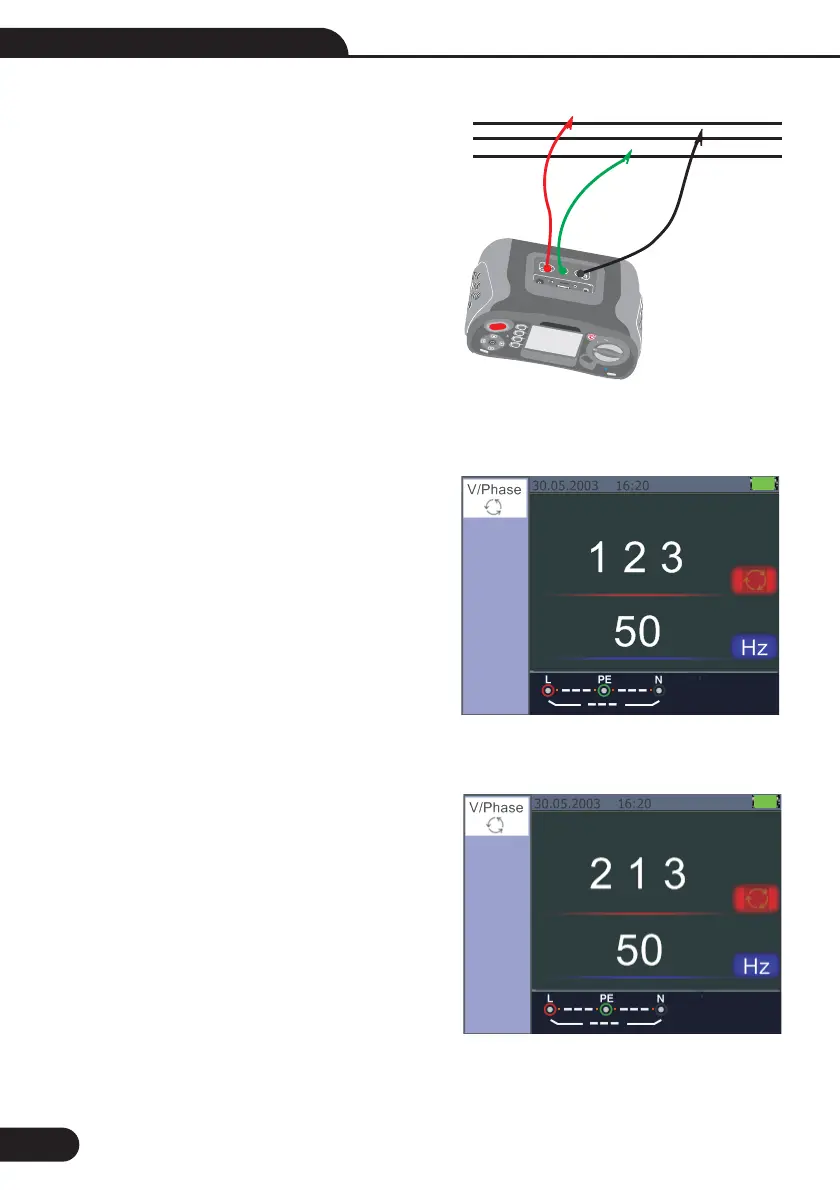
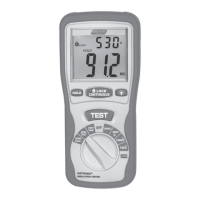
When the line conductors are connected in the
correct sequence 1.2.3 and the symbol will appear as
the
However, connected in the wrong sequence, 2.1.3
and the circle symbol will change to the symbol
displayed below
Figure 23
Figure 23 Phase Sequence screen-when
connected in clockwise direction.
Figure 24 Phase Sequence-When connected
in counter-clockwise manner
26
F1
F2
F3
F4
TEST
ESC
HLPE
B
l
u
e
t
o
o
t
h
LO
O
P
P
f
c
R
C
D
V
LO
W
O
H
M
R
E
I
N
S
U
LAT
I
O
N
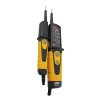
Figure 22 Phase Sequence-Test lead connection
L
N
PE
Multifunction Tester User Manual