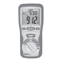
6.4-Earth Resistance Display/Switch and Terminal Settings
6.5-To Measure Earth Resistance
6.6-RE Function Menu Operation
F1 Button:
F2 Button:
F3 Button:
F4 Button:
Up Button:
Down Button:
Enter Button:
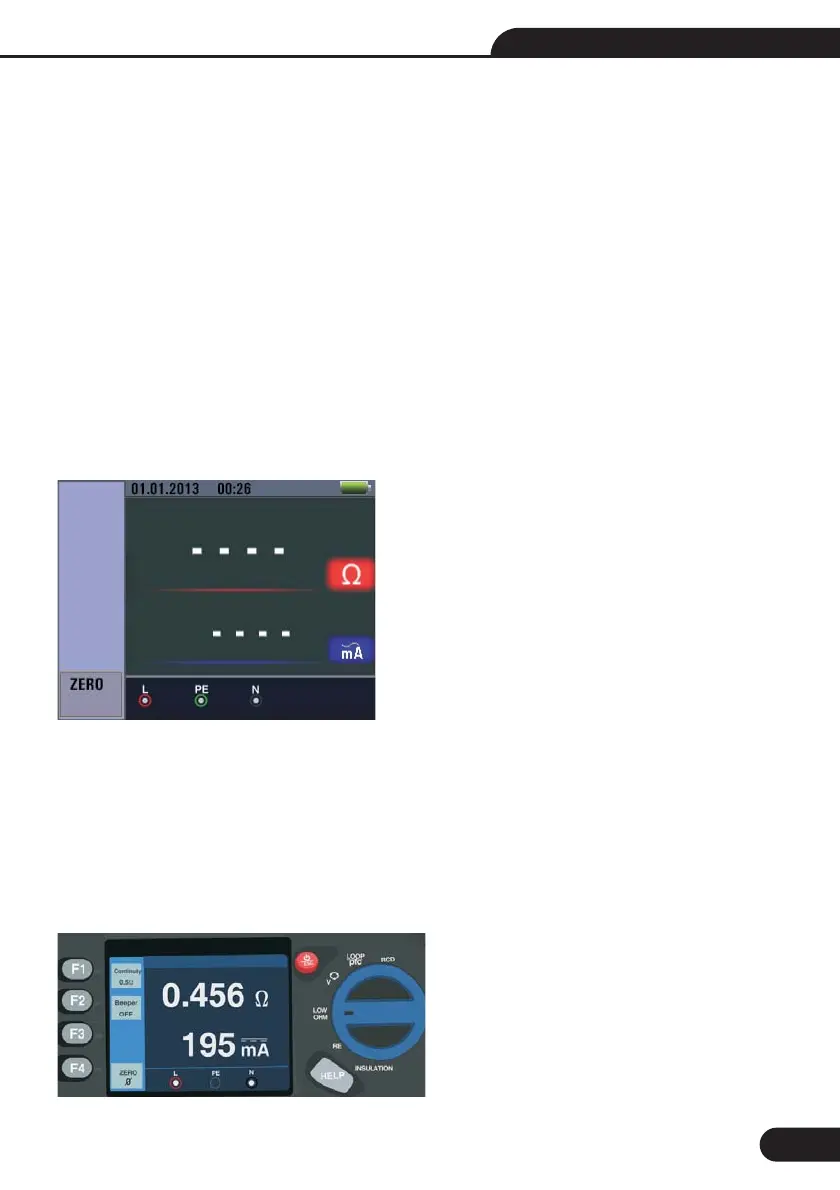
6.7-Using the LOW OHM Function
The earth resistance test is a 3-wire test consisting of two test stakes and the earth electrode under test.
This test requires an accessory stake kit. Connect as shown in right figure .
Best accuracy is achieved with the middle stake at 62 % of the distance to the far stake. The stakes should
be in a straight line and wires separated to avoid mutual coupling.
The earth electrode under test should be disconnected from the electrical system when conducting the
test. Earth resistance testing should not be performed on a live system.
Turn the rotary switch to the RE position.
Press and release TEST button. Wait for the test to complete.
The primary (upper) display shows the eart resistance reading.
The Test Current will be displayed in the secondary display.
If Voltage detected between the test rods greater than 10V, the test is inhibited.
Main Display
None
None
None
Short the F4 button 3S, triggering zero function.
None
None
None
1-
2-
29
Multifunction Tester User Manual