Fig. 152
P 42/ 45
Repair
[5] Circuit diagram, Wiring diagram
[5] -2. 110V area where Radio Interference Suppression is required
[5] -2. 3. How to connect wires
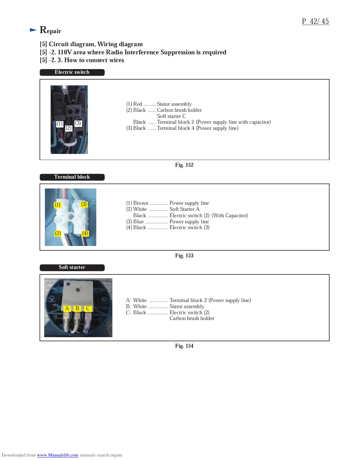
Electric switch
(1)Red ......... Stator assembly
(2) Black ...... Carbon brush holder
Soft starter C
Black ...... Terminal block 2 (Power supply line with capacitor)
(3) Black ...... Terminal block 4 (Power supply line)
Fig. 153
Terminal block
(1)
(2)
(3)
(4)
(1) Brown ............. Power supply line
(2) White .............. Soft Starter A
Black ............... Electric switch (2) (With Capacitor)
(3) Blue ................. Power supply line
(4) Black ............... Electric switch (3)
Fig. 154
Soft starter
A B C
A: White .............. Terminal block 2 (Power supply line)
B: White .............. Stator assembly
C: Black ............... Electric switch (2)
Carbon brush holder
(1)
(2)
(3)

 Loading...