EasyManuals Logo

Makita LS1017L Technical Information

Makita LS1017L
48 pages
To Next Page IconTo Next Page
To Previous Page IconTo Previous Page
Page #19 background imageLoading...
Page #19 background image
P 16/ 45
Repair
[3] DISASSEMBLY/ASSEMBLY
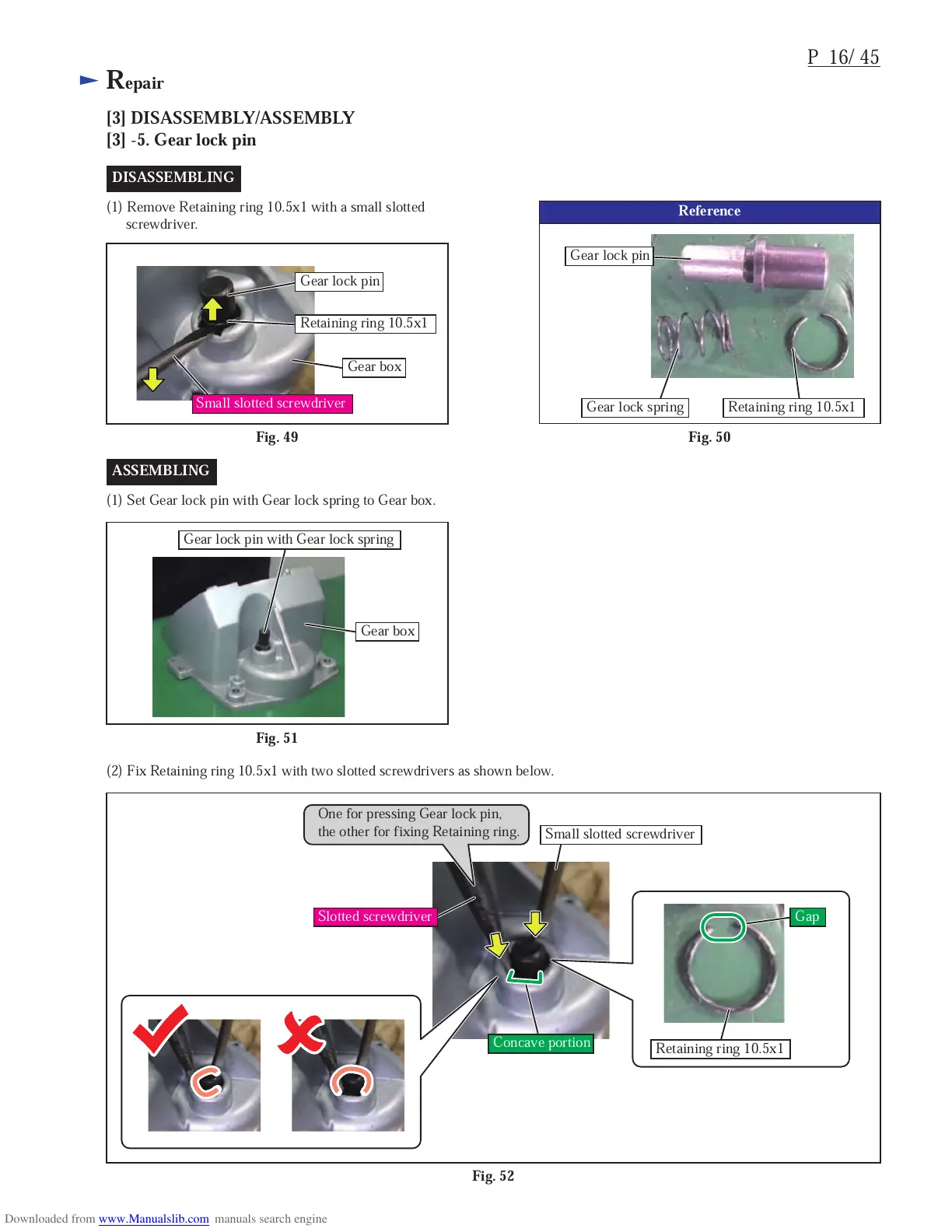
[3] -5. Gear lock pin
Fig. 49
(1) Remove Retaining ring 10.5x1 with a small slotted
screwdriver.
(2) Fix Retaining ring 10.5x1 with two slotted screwdrivers as shown below.
Fig. 50
DISASSEMBLING
Gear lock pin
Gear box
Retaining ring 10.5x1
Small slotted screwdriver
Reference
Gear lock pin
Gear lock spring Retaining ring 10.5x1
Fig. 51
(1) Set Gear lock pin with Gear lock spring to Gear box.
ASSEMBLING
Fig. 52
One for pressing Gear lock pin,
the other for fixing Retaining ring.
Gear box
Gear lock pin with Gear lock spring
Small slotted screwdriver
Retaining ring 10.5x1
Concave portion
Gap
Slotted screwdriver

Other manuals for Makita LS1017L

Questions and Answers:

Question and Answer IconNeed help?

Do you have a question about the Makita LS1017L and is the answer not in the manual?

Makita LS1017L Specifications

General IconGeneral
Blade Diameter260 mm
Laser GuideYes
Voltage240 V
Length825 mm
Width536 mm
Height633 mm
Mitre Capacity0° - 52°
No Load Speed4300 rpm
Max. Cutting Capacity at 45°68 x 197 mm
Input Wattage1, 430 W
Power Input1, 430 W

Related product manuals