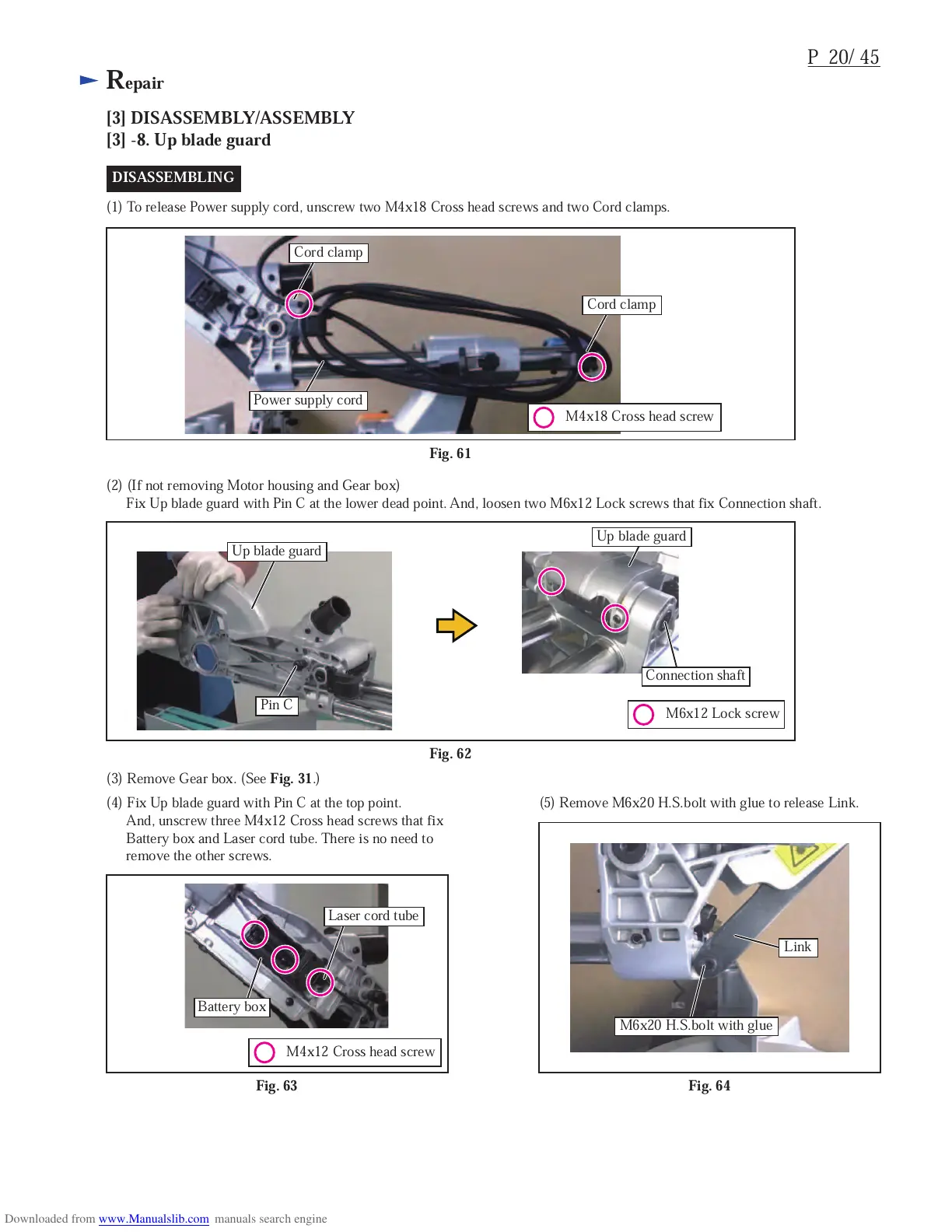
M4x18 Cross head screw
Power supply cord
Cord clamp
Cord clamp
M6x12 Lock screw
M4x12 Cross head screw
Fig. 62
(2) (If not removing Motor housing and Gear box)
Fix Up blade guard with Pin C at the lower dead point. And, loosen two M6x12 Lock screws that fix Connection shaft.
(3) Remove Gear box. (See
Fig. 31
.)
Up blade guard
Up blade guard
Pin C
Connection shaft
(4) Fix Up blade guard with Pin C at the top point.
And, unscrew three M4x12 Cross head screws that fix
Battery box and Laser cord tube. There is no need to
remove the other screws.
(5) Remove M6x20 H.S.bolt with glue to release Link.
Fig. 64Fig. 63
Battery box
M6x20 H.S.bolt with glue
Link
Laser cord tube
DISASSEMBLING
 Loading...