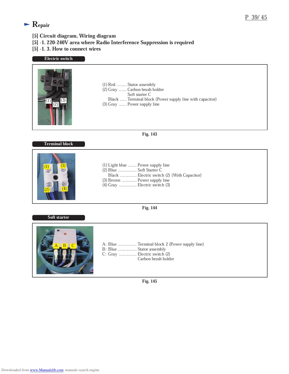
Fig. 143
P 39/ 45
Repair
[5] Circuit diagram, Wiring diagram
[5] -1. 220-240V area where Radio Interference Suppression is required
[5] -1. 3. How to connect wires
Electric switch
(1)
(2)
(3)
(1) Red ......... Stator assembly
(2) Gray ....... Carbon brush holder
Soft starter C
Black ...... Terminal block (Power supply line with capacitor)
(3) Gray ....... Power supply line
Fig. 144
Terminal block
(1)
(2)
(3)
(4)
(1) Light blue ........ Power supply line
(2) Blue ................. Soft Starter C
Black ............... Electric switch (2) (With Capacitor)
(3) Brown ............. Power supply line
(4) Gray ................ Electric switch (3)
Fig. 145
Soft starter
A B C
A: Blue ................. Terminal block 2 (Power supply line)
B: Blue ................. Stator assembly
C: Gray ................ Electric switch (2)
Carbon brush holder

 Loading...