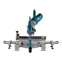
Fig. 147
P 41/ 45
Repair
[5] Circuit diagram, Wiring diagram
[5] -2. 110V area where Radio Interference Suppression is required
[5] -2. 2. Wiring diagram
Overall wiring diagram
Fig. 151
Cable tie position
Motor housing Soft starter Line filter
Motor housing complete
Note: Do not route the wires over
the housing because the wires
may be pinched.
Cord clamp
Capacitor
Terminal block
Brake system switch
Electric switch
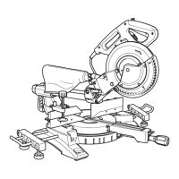
Fig. 148 Fig. 149 Fig. 150
Bundle the wires of motor
side with a cable tie.
Bundle the wires of motor
side with a cable tie.
Bundle all the wires
with a cable tie.
Bundle all the wires
with a cable tie.

 Loading...