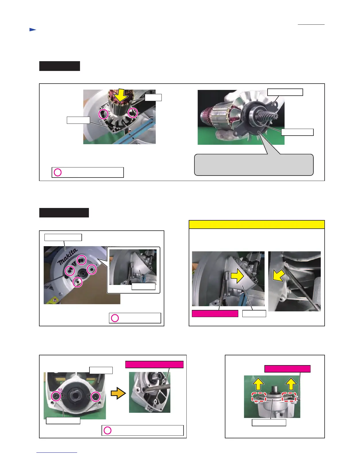
Gear box
Rotor
Shaft fix cover
M6x15 Countersunk head bolt
Bearing cover
Gear box
No.3 Phillips screwdriver
Fig. 33 Fig. 34
(3) Remove Bearing cover by prying it off
with a slotted screwdriver.
(2) Unscrew two M6x15 Countersunk head bolts with
No.3 Phillips screwdriver.
When inserting Rotor, be careful of the position of
Shaft fix cover. And check visually that the Bearing
6003 is inserted all the way into Gear box.
[3] -4. Gear box
DISASSEMBLING
M5x18 Cross head screw
Fig. 31
Fig. 32
(1) Unscrew four M6x22 H.S.bolts and remove Gear box.
M6x22 H.S.bolt
Bearing 6003
Up blade guard
If Gear box is not removed easily, use a slotted screwdriver
to pry it off.
Note
Gear box
Slotted screwdriver
Gear box
Slotted screwdriver
Bearing cover
 Loading...