P 7/ 45
Repair
[3] DISASSEMBLY/ASSEMBLY
[3] -1. Switch (cont.)
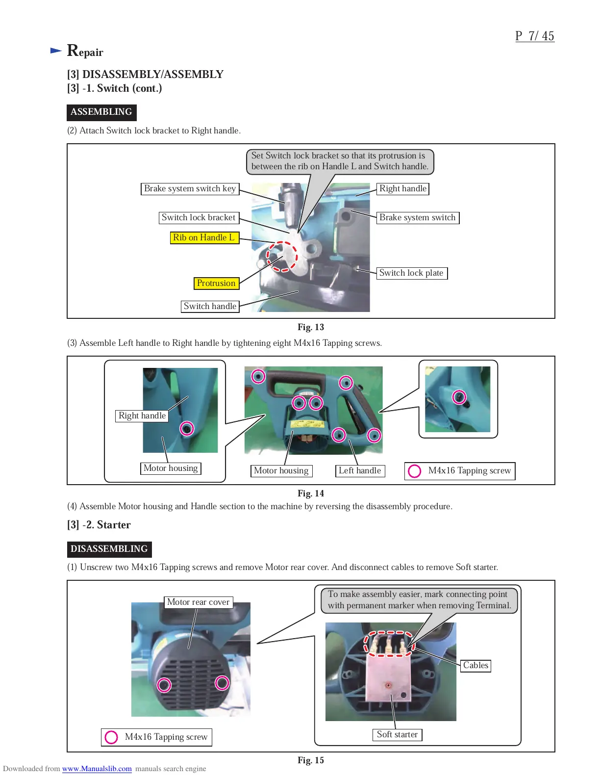
ASSEMBLING
(2) Attach Switch lock bracket to Right handle.
Fig. 13
[3] -2. Starter
Fig. 15
Fig. 14
(3) Assemble Left handle to Right handle by tightening eight M4x16 Tapping screws.
(4) Assemble Motor housing and Handle section to the machine by reversing the disassembly procedure.
DISASSEMBLING
(1) Unscrew two M4x16 Tapping screws and remove Motor rear cover. And disconnect cables to remove Soft starter.
M4x16 Tapping screw
M4x16 Tapping screw
Brake system switch key
Switch handle
Right handle
Motor housing
Left handle
Motor rear cover
Soft starter
Cables
Motor housing
Brake system switch
Right handle
Switch lock plate
Rib on Handle L
Protrusion
Switch lock bracket
Set Switch lock bracket so that its protrusion is
between the rib on Handle L and Switch handle.
To make assembly easier, mark connecting point
with permanent marker when removing Terminal.
 Loading...