P 6/ 45
Repair
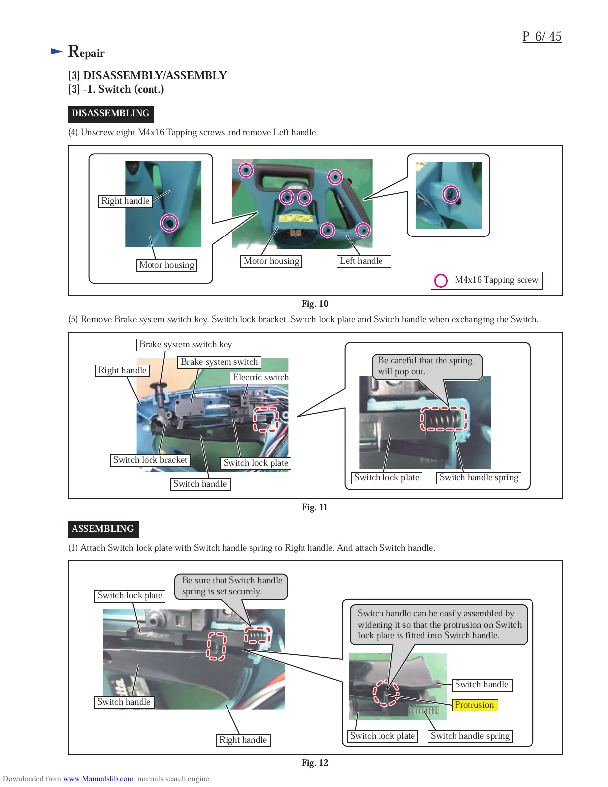
Fig. 10
[3] DISASSEMBLY/ASSEMBLY
[3] -1. Switch (cont.)
DISASSEMBLING
(4) Unscrew eight M4x16 Tapping screws and remove Left handle.
ASSEMBLING
(1) Attach Switch lock plate with Switch handle spring to Right handle. And attach Switch handle.
Fig. 11
(5) Remove Brake system switch key, Switch lock bracket, Switch lock plate and Switch handle when exchanging the Switch.
Fig. 12
Right handle
Left handle
Brake system switch key
Right handle
Right handle
Brake system switch
Switch lock bracket
Switch handle
Switch handle
Switch handle
Protrusion
Switch lock plate
Switch lock plate
Switch lock plate
Switch lock plate Switch handle spring
Switch handle spring
Electric switch
Motor housing
Motor housing
Be sure that Switch handle
spring is set securely.
Switch handle can be easily assembled by
widening it so that the protrusion on Switch
lock plate is fitted into Switch handle.
Be careful that the spring
will pop out.
M4x16 Tapping screw
 Loading...