P 27/ 45
Repair
[3] DISASSEMBLY/ASSEMBLY
[3] -9. Support arm (cont.)
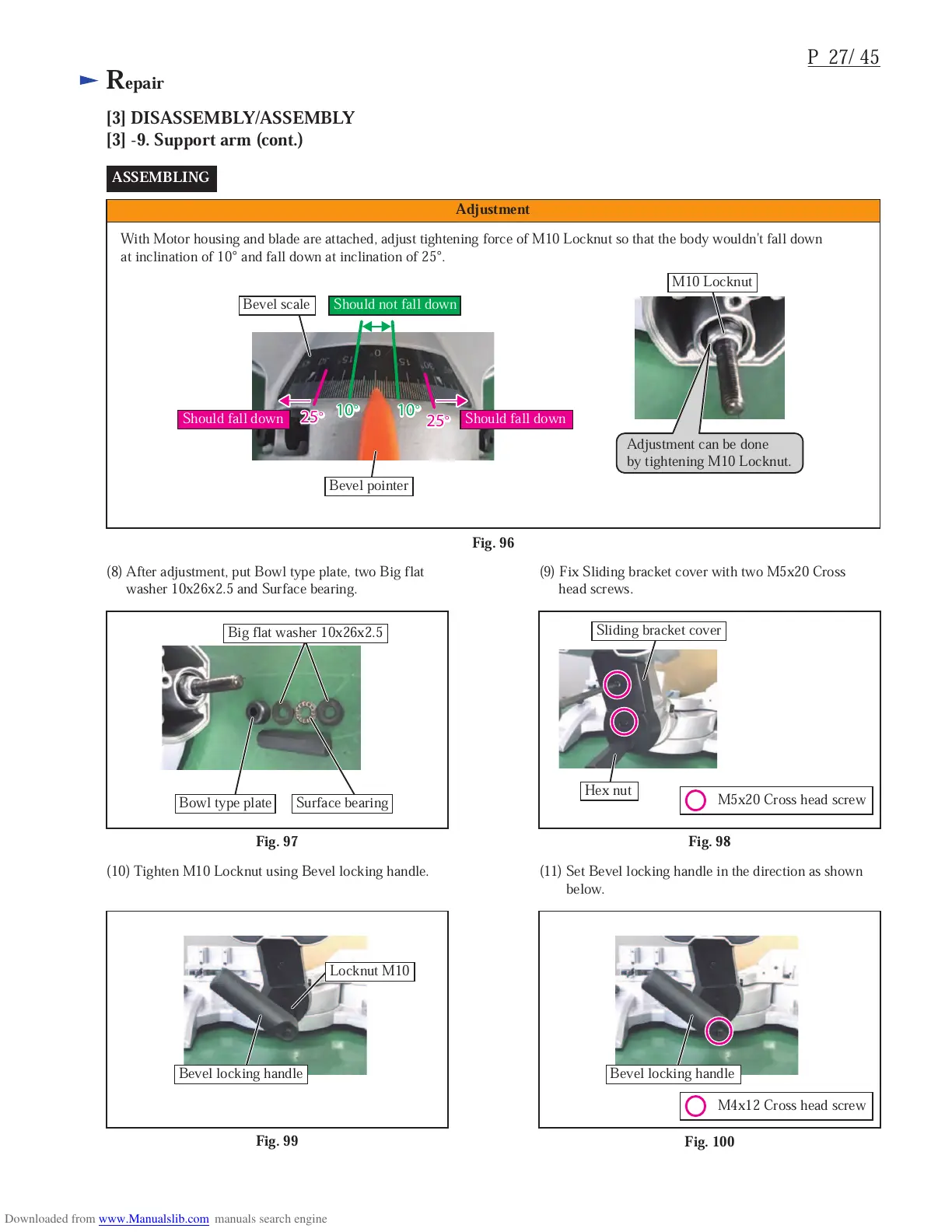
With Motor housing and blade are attached, adjust tightening force of M10 Locknut so that the body wouldn't fall down
at inclination of 10° and fall down at inclination of 25°.
ASSEMBLING
Fig. 97
Fig. 98
(8) After adjustment, put Bowl type plate, two Big flat
washer 10x26x2.5 and Surface bearing.
(9) Fix Sliding bracket cover with two M5x20 Cross
head screws.
Bevel scale
M10 Locknut
Bowl type plate
Big flat washer 10x26x2.5
Surface bearing
Bevel locking handle
Hex nut
Sliding bracket cover
M5x20 Cross head screw
M4x12 Cross head screw
Fig. 99
Fig. 100
(10) Tighten M10 Locknut using Bevel locking handle.
Locknut M10
Bevel locking handle
(11) Set Bevel locking handle in the direction as shown
below.
Adjustment can be done
by tightening M10 Locknut.
Fig. 96
Adjustment
Should not fall down
Should fall downShould fall down
10
°
25
°
25
°
10
°
10
°
25
°
25
°
10
°
Bevel pointer
 Loading...