CYLINDERHEAD
Installingthecylinderhead
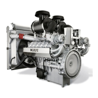
Checkingthecylinderlinerstandout
•PlacetheMeasuringplate[81](2)onthecylinder
liner
•ScrewinandtightentheHexagonshankbolt[82]
(4)withWasher[83]
•PlacetheDialgaugeholder[79](5)withDial
gauge[80](3)ontheMeasuringplate[81](2)
•Placethedialgaugetip(1)onthecrankcase
•ZerotheDialgauge[80](3)
•Carefullyplacethedialgaugetip(1)onthe
cylinderlinerandnotethedifferenceonthedial
gauge
Thepermittedcylinderlinerstandoutis0.035–
0.085mm.
Ifthecylinderlinerstandoutisoutoftolerance,t
anewcylinderliner/crankcase,seeCheckingthe
cylinderliner,372.
Puttingonthecylinderhead
•Placethenewcylinderheadgasket(1)overthe
alignmentpins
•Placethecylinderhead(2)overthealignmentpins
•ThinlyapplyWhiteTassemblypasteonthe
contactsurfaceofthenewcylinderheadbolts(1)
•Screwinthecylinderheadbolts(3)
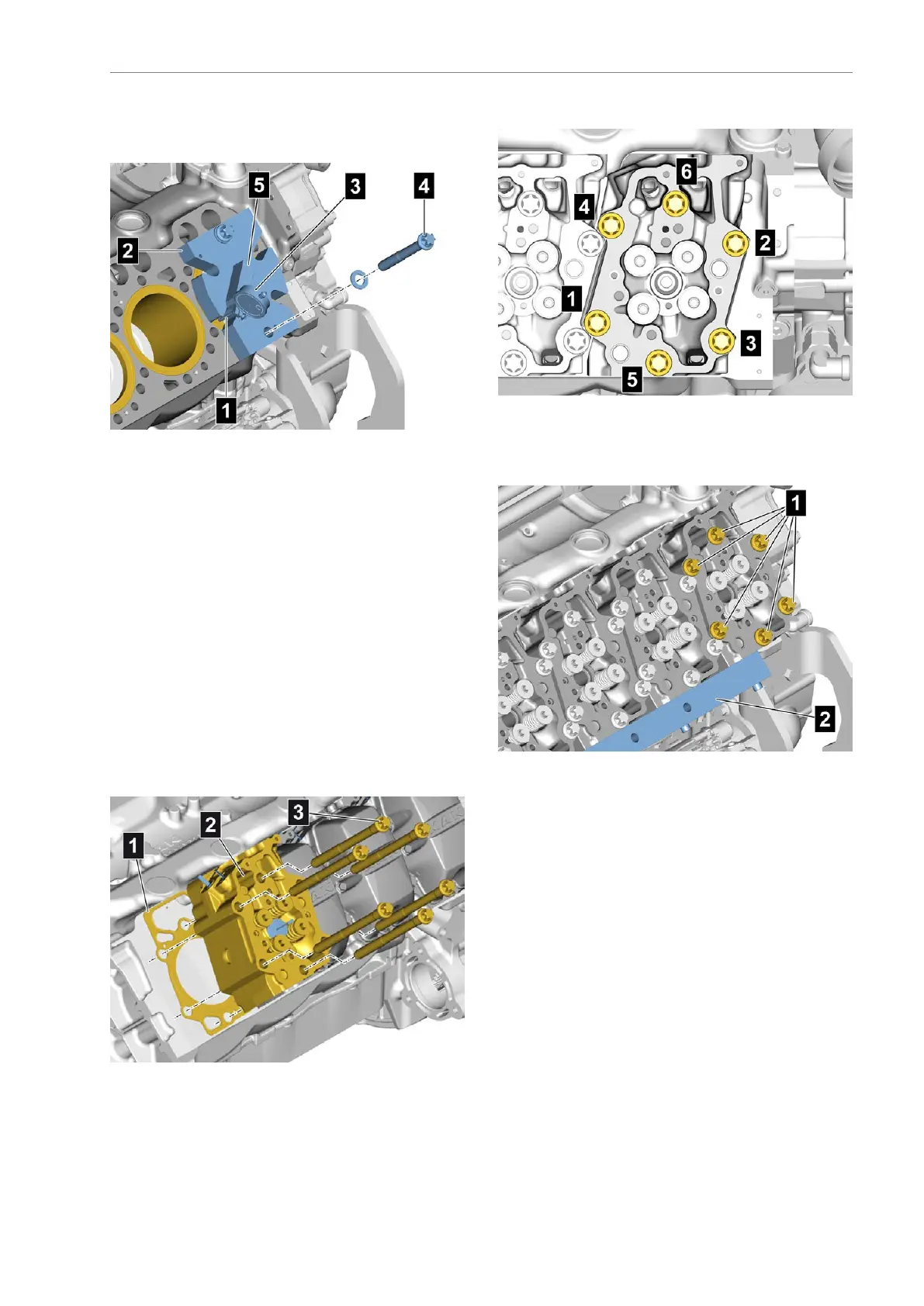
Tighteningsequenceforcylinderhead
•Screwinthecylinderheadboltsandtightenuntil
nger-tightinthetighteningsequence1to6
Pre-tighteningthecylinderheadbolts
•AttachtheAligningbar[78](2)ontheexhaustside
ofthecylinderheads
•Tightenthecylinderheadboltsasperthe
tighteningsequenceusingasocketandatorque
wrench
•Tightenthecylinderheadbolts(1)toInitialtorque
50Nm
•Tightenthecylinderheadbolts(1)to2ndtorque
150Nm
•Tightenthecylinderheadbolts(1)to3rdtorque
300Nm
AE63stedition229
 Loading...