SET-UP AND INSTALLATION 18000 OPERATOR MANUAL
4-28
Published 12-05-17, Control # 032-23
Legend for Figure 4-18
NOTE 1 Loop together for shipping.
NOTE 2 Loop together for shipping. Can be connected
one way only (see NOTE 6).
NOTE 3 Loop together for shipping. Hoses must run in a
straight line between rotating bed and adapter
frame (see NOTE 6).
NOTE 4 Loop hoses in mast together for shipping. Can
be connected one way only.
NOTE 5 Hoses run in a straight line between boom butt
and rotating bed (see NOTE 6)
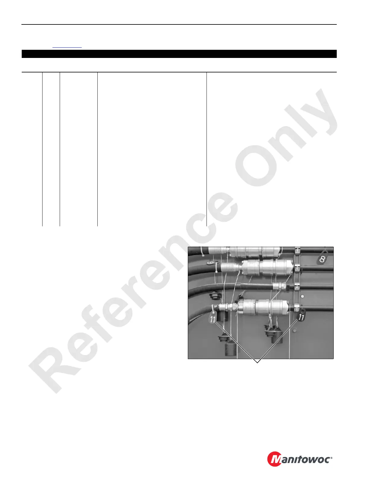
NOTE 6 On current production cranes, hydraulic hoses
and corresponding couplers have numbered
tags (see View L). Match numbers to ensure
proper hose connection.
View ID Type Purpose Comment
Ends of all disconnected cables and hoses must be covered with closures
or sealing caps (or looped together) to protect them from water and dirt.
A 1 Electric Cable From Rot Bed Node 6 Connect to cable (3) when connecting rotating bed
to adapter frame.
2 Electric Terminating Plug Must be plugged to cable (1) until rotating bed is
connected to adapter frame.
B 3 Electric Cable From Adapter Frame Node 7 Connect to cable (1) when connecting rotating bed
to adapter frame.
4 Electric Boom Cable from Adapter Frame Node 7 Connect to cable (WN18) from boom Node 8 when
connecting boom butt to rotating bed.
5 Electric Terminating Plug Must be plugged to cable (4) until boom butt is
connected to rotating bed and all cables are
connected in boom.
C — Hydraulic Adapter Frame to Carbody 4 hoses right side; 6 hoses left side (NOTE 1).
D — Grease Lubricate Crawler 2 lines each crawler (NOTE 2).
E — Hydraulic Rotating Bed Rear Jack 2 hoses each side (NOTE 2).
F, G — Hydraulic Rotating Bed/Adapter Frame 6 hoses left side; 5 hoses right side (NOTE 3).
H 6 Hydraulic Rotating Bed Front Jack 2 hoses each side (NOTE 2).
H 7 Hydraulic Drum 4 (Boom Hoist) in Mast Butt 2 hoses each side (NOTE 4).
I Hydraulic Drum 4 (Boom Hoist) in Mast Butt 2 hoses left side (left side shown); 3 hoses right
side (NOTE 4).
J Hydraulic Drums in Boom Quantity on front of rotating bed varies (NOTE 5).
K 8 Electric Drum 4 (Boom Hoist) in Mast Butt 2 Receptacles.
Match numbers to ensure
proper hose connection.
View L
P1947h
 Loading...


