SET-UP AND INSTALLATION PROCEDURES RT530E-2 OPERATOR’S MANUAL
4-8 Published 5-3-2016, Control # 555-02
1. Visually check to ensure all pins are installed.
2. Crane should be set up on outriggers using normal
setup procedures. Refer to Section 3 - OPERATING
CONTROLS and PROCEDURES.
a. Fully retract boom.
b. Lower boom to horizontal for erecting over the front
of the crane.
NOTE: The auxiliary boom nose (rooster sheave) does not
have to be removed. However, if reeved, the hoist
cable must be removed from the sheave.
3. Rig either the main hoist or optional auxiliary hoist cable
for single part line with nothing but the wedge socket on
the end of the cable. Refer to CABLE REEVING and
DEAD END RIGGING in this section.
4. Remove the retainer clips from the right side attachment
pins (6) (Figure 4-7) (Figure 4-10) stowed in the base of
the boom extension and remove the attachment pins
from the boom extension (2) (Figure 4-7) (Figure 4-10).
Insert the right side attachment pins through the boom
attachment and boom extension anchor fittings. Install
the retainer clips in the attachment pins.
5. Remove the retaining pin from the hitch pin that secures
the boom extension to the rear stowage bracket
(Figure 4-12) (Detail A). Remove the hitch pin, unlocking
the boom extension from the boom.
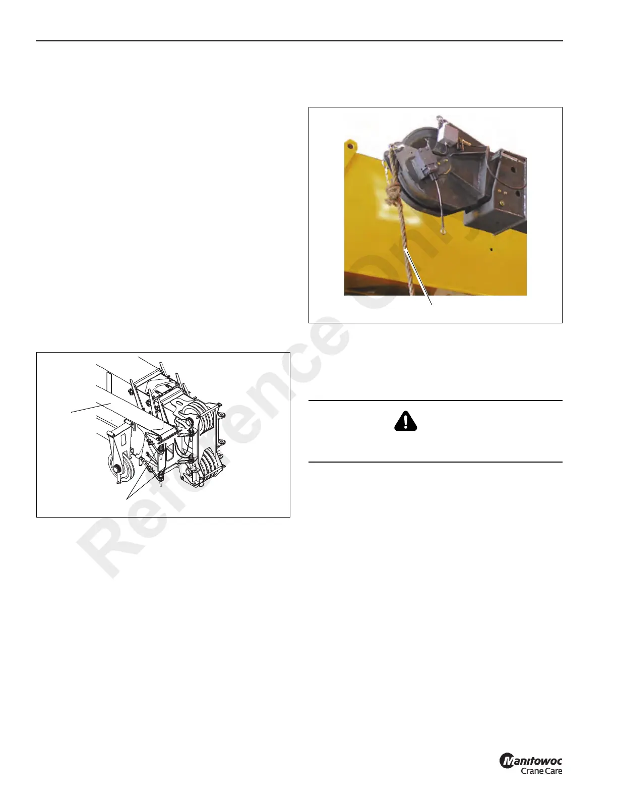
6. Attach a length of rope to the boom extension tip
(Figure 4-8) to aid in swinging the boom extension into
place ahead of the boom nose.
7. Raise the boom to horizontal and extend the boom
approximately 51 to 64 cm (20 to 25”). Make certain that
the boom extension stowage lugs clear the guide pins
and ramp on the front (Figure 4-12) (Detail B) and rear
(Figure 4-12) (Detail A) stowage brackets.
8. Slightly raise and/or lower the boom to help control the
boom extension. Using the rope attached to the tip of the
boom extension, manually swing the extension into
place ahead of the boom nose (Figure 4-9), engaging
the attachment fittings with the anchor fittings on the left
side of the boom nose.
DANGER
When erecting the boom extension, ensure that all
personnel and equipment are kept clear of the swing path.
Reference Only
 Loading...


