Manitowoc Published 10-09-2020, Control # 259-06 2-11
MLC80A-1/MLC90A-1/MLC100A-1/MLC100-1 SERVICE/MAINTENANCE MANUAL HYDRAULIC SYSTEM
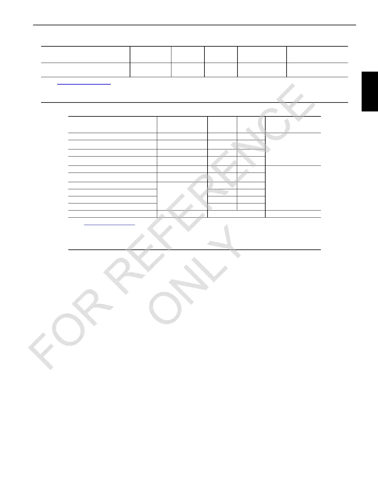
Table 2-1. Closed-Loop Circuit Hydraulic Specifications
Table 2-2. Open-Loop Circuit Hydraulic Specifications
Function
1
Speed
1
RPM
Pump
Port
Motor
Port
Pressure
3
Bar (PSI)
Charge Pressure
Bar (PSI)
Swing Left
1.8 to 2
BB
320 (4,640) 30 (435)
Swing Right A A
1
See Figure 2-1 on page 1 for pump identification.
2
Speeds are based on high engine idle and handles moved fully forward or back. Speeds can vary plus or minus 5%.
3
Pressures are controlled by relief valves in each pump.
Function
1
Speed
2
RPM
Valve
Port
Motor
Port
Pressure
Bar (PSI)
Drum 1 and 2 Hoist 41 to 45 A A
375 (5,440)
Drum 1 and 2 Lower
See
3
BB
Drum 3 Hoist 34 to 38 A A
Drum 3 Lower
See
3
BB
Drum 4 Hoist 17 to 19 A A
320 (4,641)
Drum 4 Lower
See
3
BB
Right Travel Reverse
5.5 to 6.9 at
Tumbler
BA
Right Travel Forward A B
Left Travel Reverse A A
Left Travel Forward B B
Accessories NA NA 315 (4,568)
1
See Figure 2-11, page 8 for valve identification.
2
Speeds are based on high engine idle, no rope on drums, and handles moved fully forward or back. Speeds
can vary plus or minus 5%.
3
Lowering speeds may be up to 10% slower than hoist speeds.
 Loading...


