– User and Installation Manual
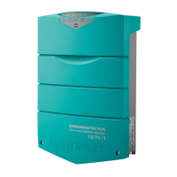
• Connect the AC output L1, N and PE of the Primary (L1) and Replica 1 (L1) unit in parallel by means
of a busbar. The cables length and wire gauge must be identical.
• Connect the AC output L2, N and PE of the Replica 2 (L2) and Replica 3 (L2) unit in parallel by
means of a busbar. The cable length and wire gauge must be identical.
• The AC output of each CombiMaster Inverter/Charger must be protected by means of properly sized
circuit breakers (85Amax) that switch off simultaneously L1, L2 and Neutral.
Figure 17: wiring split-phase + parallel AC OUT
All AC loads must be protected by means of properly sized circuit breakers and a Ground Fault Circuit
Interrupter (GFCI).
7.6 Network wiring
7.6.1 Preparation
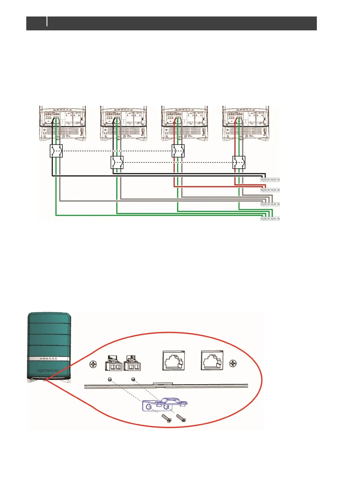
Parallel Current Sharing and cluster Communication cables are relatively short because stacked units
should be installed in close proximity to each other. Connect the optional strain relief for parallel Current
Sharing cables with two bolts to the bottom of the CombiMaster Inverter/Charger.
Figure 18: Attaching the strain relief at the bottom of a CombiMaster Inverter/Charger