24
|
EN / SunMaster CS15TL RP / CS20TL RP / CS30TL RP
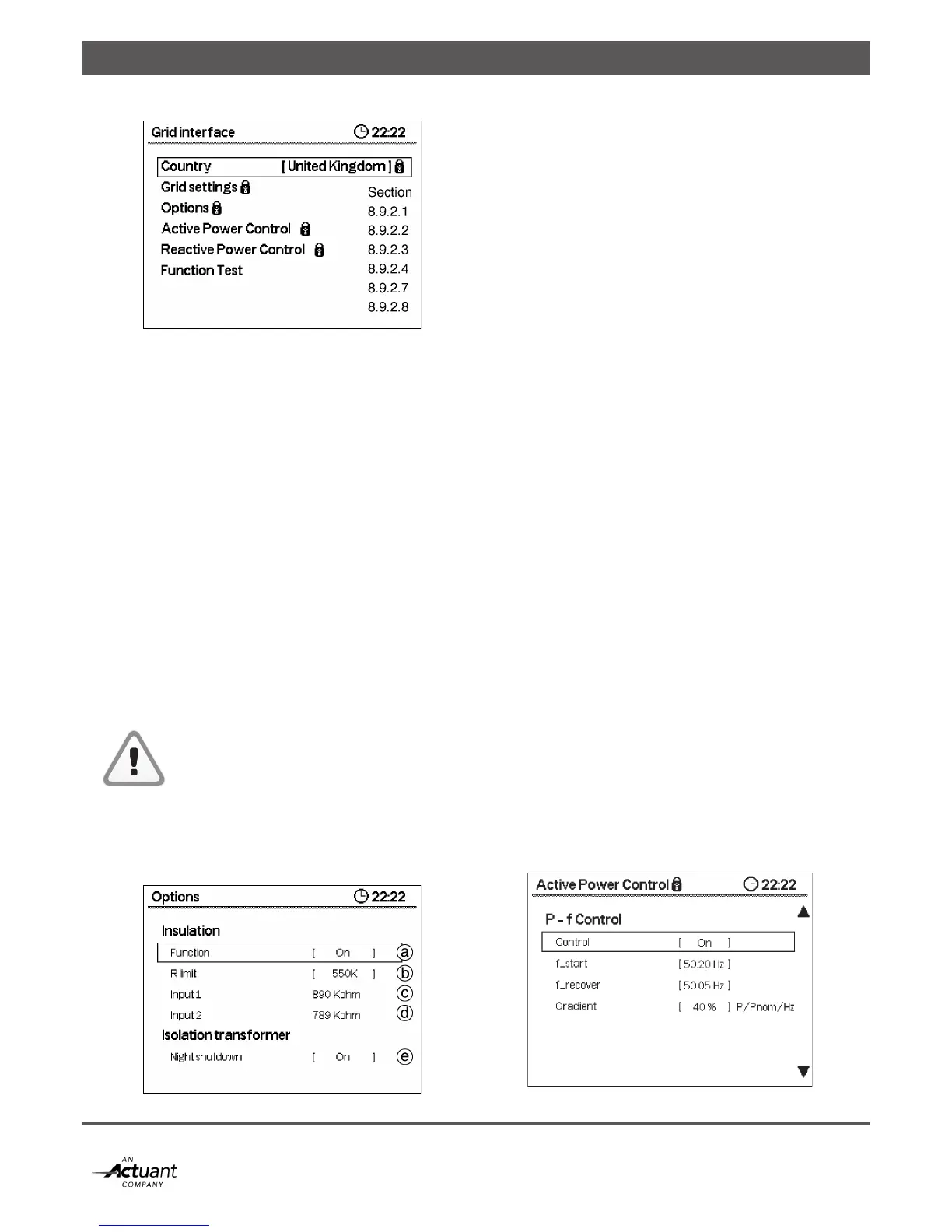
Figure 8-18: Grid Interface
• Country. The currently selected installation country. The
SunMaster CS supports all countries listed in chapter 10.
• Grid Settings. The grid protection settings for the
currently selected country
• Options. Isolation fault detection and transformer control
• Active Power Control. Options to allow controlling the
inverter active power output.
• Reactive Power Control. Options to allow controlling
the inverter reactive power output.
8.9.2.1 Grid Settings
For every country listed in the country table, Mastervolt has
prepared a default set of parameters to comply with the grid
code applicable for that country. These settings do not
need to be adjusted in any normal case. Only if absolutely
necessary, or if the installation country is not listed (yet),
the grid settings can be modified in this menu. If the grid
settings for a country are modified, the inverter will
automatically show “Custom” as the selected country.
Selecting the original country again will revert the inverter
to the default country settings.
Changing the grid settings should not be done
under normal circumstances. Without prior
written permission from Mastervolt, changing
these settings will void the warranty and could
void compliance to the national grid codes.
8.9.2.2 Options
The options menu controls the Insulation Fault detection and
the isolation transformer relay. Refer to figure 8-19.
Figure 8-19: Options
Insulation
a. Function. Describes how the insulation detection should
respond to a fault. There are several options:
On For normal installations. Inverter will shut down in case of
insulation failure. (Default Setting)
Neg GND For functional grounding on the Negative PV
Terminals. Inverter will shut down in case the
grounding is released.
Pos GND For functional grounding on the Positive PV
Terminals. Inverter will shut down in case the
grounding is released.
Input 2 NC Setting to operate the inverter with input 2 not
connected. Inverter will shut down in case of
insulation failure on Input 1.
Input 1 NC Setting to operate the inverter with input 1 not
connected. Inverter will shut down in case of
insulation failure on Input 2.
Off Ignore insulation failures.
Setting the Insulation Detection to OFF may present a safety
hazard in case the insulation fails. It is not recommended to
use this setting unless absolutely necessary.
b. R limit. This value sets the limit below which the inverter
will show an inverter failure. Depending on the inverter
model, the limits are different:
For detailed information about insulation detection levels,
please visit the Mastervolt website.
c. Input 1. In this screen, the last insulation measurement
results for input 1 are shown. Refer to section 9.1.
d. Input 2. In this screen, the last insulation measurement
results for input 2 are shown.
Isolation Transformer
e. Night Shutdown. Set this option to off (default) to disable
transformer control. When set to ON, the inverter will switch
the transformer off during the night to save energy.
8.9.2.3 Active Power Control
The CS inverter can reduce its active power output under
several circumstances, such as the grid frequency. The
active power control settings can be used to change the
inverter behaviour.
Figure 8-20: Active Power Control configuration