|
25
EN / SunMaster CS15TL RP / CS20TL RP / CS30TL RP
8.9.2.4 DNO Power Control
For some PV installations, the local grid operator (Distribu-
tion Network Operator, DNO) may require the possibility to
reduce the power output of the PV plant by remote com-
mands. In such case, a Telecontrol receiver must be in-
stalled. Refer to section 10.3.1.
8.9.2.5 Frequency dependent Power Control
The SunMaster CS can reduce its output power
autonomously if the grid frequency exceeds the nominal
value. Refer to section 10.3.2.
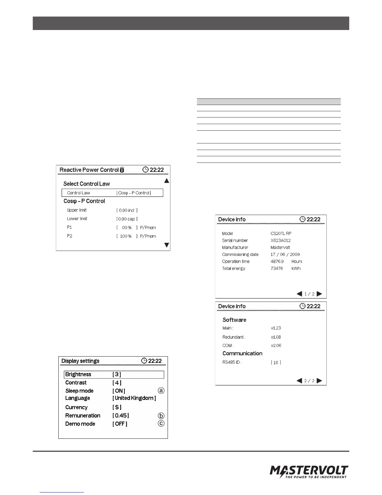
8.9.2.6 Reactive Power Control
The CS inverter can produce reactive power with different
control mechanisms. The reactive power control settings
can be used to change the inverter behaviour. Refer to
section 10.5.
Figure 8-21: Reactive Power Control configuration
• Select control law
• Cos-phi control
• Constant cos-phi
• Q-U control
• Constant Q
8.9.2.7 Function test
This option only appears if you selected Country code Italy.
Refer to chapter 10.2
8.9.3 Display Settings
This menu allows to adjust the user preferences for the
Display. Refer to figure 8-22.
Figure 8-22: Display settings
a. Sleep Mode. Sleep mode switches off the backlight, and
returns the display to the Home Screen, when no buttons
are pressed for more than 5 minutes
b. Remuneration. Set this value to the price per kWh ap
plicable for the installation
c. Demo Mode. Shows samples for some measurements.
Table with display settings ranges
Display Settings
Setting Range
Brightness 1 – 5
Contrast 1 – 5
Sleep Mode On, Off
Language English, Dutch, Spanish,
Italian, French, German
Currency $ , €
Remuneration 0.00 – 9.99
Demo Mode On, Off
8.9.4 Device Info
These screens show the inverter model, serial number and
firmware revision numbers.
The commissioning date is the date when more than 10 kWh
has been produced or when more than 30 operating hours
have been accumulated.
Figure 8-23: Device information
8.9.5 Alarm Contact Settings
The alarm contact settings allow to configure the
potential-free alarm contact available in the communication
drawer. Refer to section 7.7 for connection examples
using the alarm contact.