INSTALLATION
10 November 2006 / Masterlink BTM-III / EN
4 INSTALLATION
WARNING
During installation and commissioning of
the Masterlink BTM III, the Safety
Guidelines and Measures are applicable
at all times. See chapter 2 of this manual.
CAREFUL!
Wrong connections may cause damage
to the Masterlink BTM III which is not
covered by guarantee!
4.1 THINGS YOU NEED FOR INSTALLATION
Tools:
A saw to make a cut-out in the instrument panel
A 6mm drill to make a hole in the back of the
installation housing.
A wire cutter / stripper
A crimping tool for cable terminals
A cross-head screw driver
2 mm and 5 mm flat blade screwdrivers.
A complete set of spanners, pliers and wrenches
may be helpful during the installation of the
Masterlink BTM III
Materials:
; The Masterlink BTM-III panel (included)
; Grey installation housing (included)
; A 500Amp/50mV shunt (included). This shunt
will only be applied for the current measurement
of battery set 1. Current measurement for
battery set 2 and 3 is not possible. For higher
nominal currents a shunt up to 1000A/100mV
may be applied instead (not included, see
ordering information)
2x0.25mm² twisted pair wire, long enough to
reach from the shunt to the Masterlink BTM-III
panel
Wires 0.25mm² for voltage sensing of each
battery set and for the DC power supply of the
Masterlink BTM-III panel
Fuse holders with 2 A-T fuses to be integrated in
the voltage sensing line to each battery set.
As short as possible heavy duty battery cable,
finished with cable lugs, to run from the minus
pole of the battery to the shunt. Cable thickness
must be in accordance with the electrical
installation
Option: an external alarm relay. Specifications:
max current consumption: 100mA, Nominal
voltage: same as the DC power supply.
4.2 INSTALLATION STEP BY STEP
Disconnect the electrical power:
• Switch off all consumers,
• Switch off all charging systems.
• Remove all battery fuses.
• Check with a suitable voltmeter whether the entire DC installation is voltage
free.
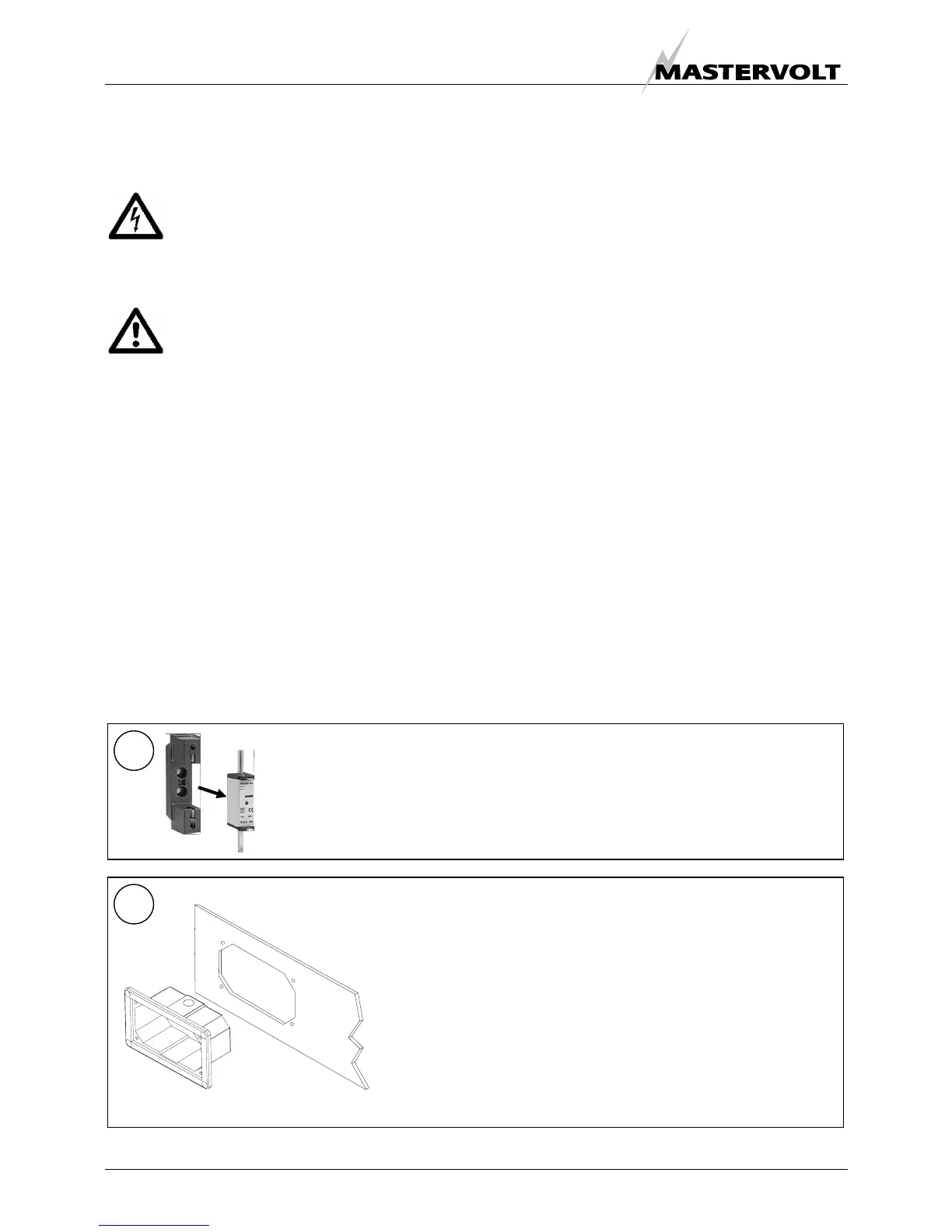
1
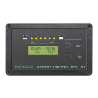
Mounting of the panel
The Masterlink BTM III panel should be placed as close as possible
to the batteries. Maximum distance: 25 meters.
• Make a cut out in the instrument panel using the outline drawings
of chapter 13 or using the mounting template of the box in which
the Masterlink BTM III was delivered. Do not use the grey
installation housing if you want to integrate the Masterlink BTM III
in your Mastervision panel. For good visibility avoid installing the
panel in direct sunlight
• Drill a hole in the back of the grey installation housing, on the
side where it is easy to enter the cables
2