INSTALLATION
EN / Masterlink BTM-III / November 2006 11
Notes:
• Connection of batteries 2 and 3 is optional
• Keep all wires as short as possible
• Keep wiring away from other noise producing
conductors
• Take adequate measures to avoid corrosion of the
wires and connections
• Do not exchange the wiring of the load side with the
battery side
4
Load side
Battery side
Battery bank 1
(Service battery)
Battery bank 2 Battery bank 3
Masterlink BTM III
Rear view
Fuse 2A-T
Fuse 2A-T
Fuse 2A-T
Connect the Masterlink BTM III as indicated below, but do not place the 2A-T fuses of the
voltage sense wires yet!
Voltage sense
wires
Battery side
Load side
+ – + – + –
Battery cables must be
connected here
Twisted wires must
be connected here
Twisted wires
LOW BATT RLY
+ BATTERY 3
+ BATTERY 2
+ SERVICE BATTERY
SHUNT BATT SIDE
SHUNT LOAD SIDE
GROUND
+ POWER SUPPLY
DC power
supply
8…50VDC
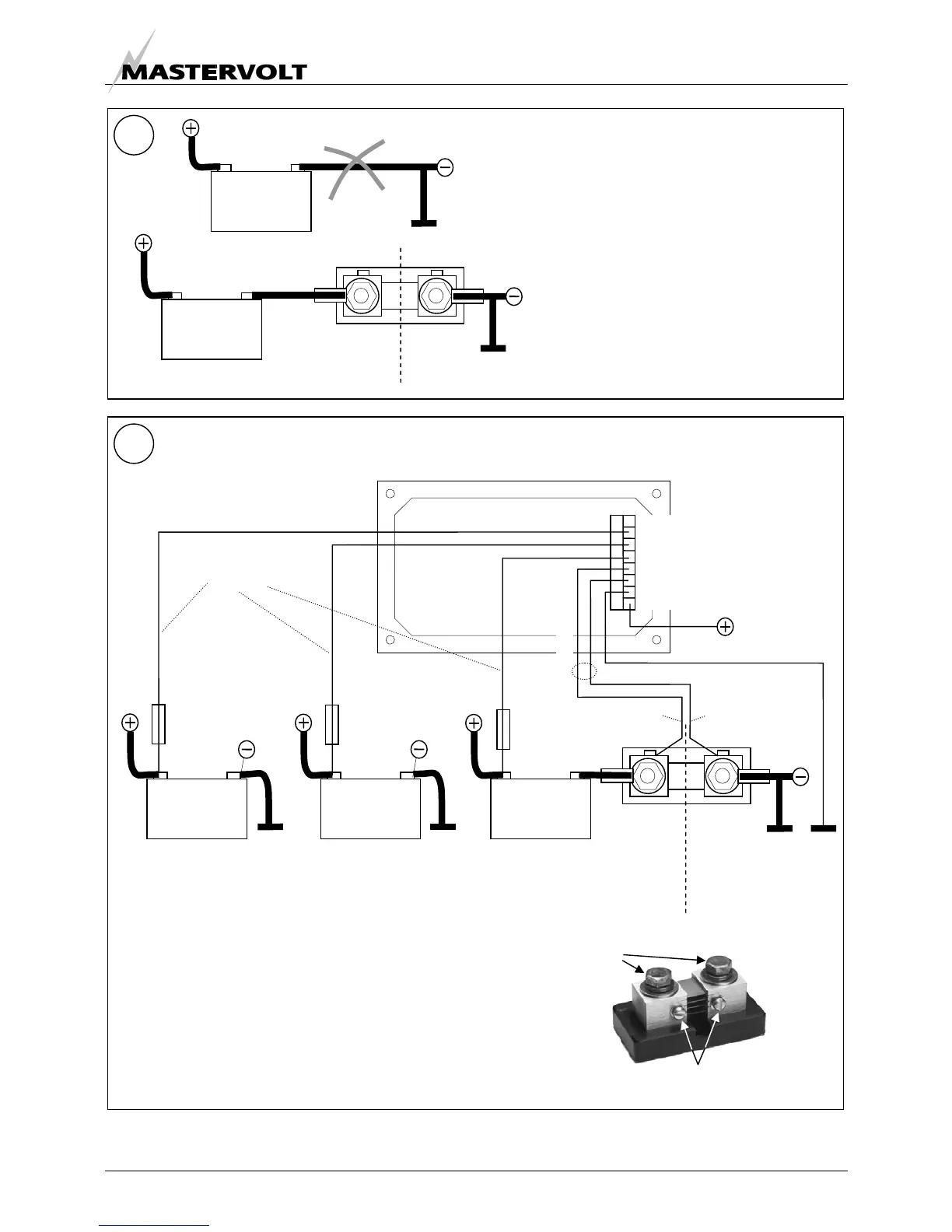
Wiring of the shunt (battery bank 1 only)
• Disconnect the wiring from the
negative battery pole
• Place the shunt between the negative
wires and the negative battery pole
using the heavy duty battery cable
Note: If several minus cables were
connected to the negative battery pole,
make sure that all these cables are
connected at the load side of the shunt
3
Load side
+ –
Battery side
+ –