INSTALLATION
12 November 2006 / Masterlink BTM-III / EN
Commissioning
If all wiring is OK:
• Install the 2 A-T fuses of the voltage sense wires
• Place all battey fuses.
• Proceed with chapter 5, “FIRST START-UP” to synchronize the Masterlink
BTM III in accordance with the electrical installation.
7
Option: Connect the alarm
relay as indicated
5
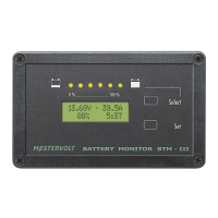
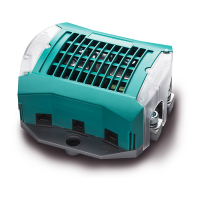
Masterlink BTM III
Rear view
DC power supply
Options:
Option: Instead of connecting a
battery, the DC-input for battery
bank 3 can be also be
connected to the control circuit
of the dashboard lightning (3-
35V). Then the backlight of the
Masterlink BTM-III will operate
simultaneously with the
dashboard lightning.
See chapter 9.1 for settings
Option: Here a 6-pole RJ12 connector can be found for serial
communication. Protocol QRS232. See chapter 11.6 for more
information
LOW BATT RLY
+ BATTERY 3
+ BATTERY 2
+ SERVICE BATTERY
SHUNT BATT SIDE
SHUNT LOAD SIDE
GROUND
+ POWER SUPPLY
Check all wiring.
Then mount the panel into the grey
installation housing
6
Mount this assembly into the
instrumentation panel