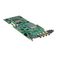
The Matrox Solios eV-CL is a high-performance Camera Link frame grabber, available in several versions: PCIe dual-Base/single-Medium (eV-CLB and eV-CLBL) and PCIe single-Medium/single-Full (eV-CLF and eV-CLFL). The eV-CLBL and eV-CLFL versions include the same auxiliary connectors as the original Matrox Solios eCL board.
Function Description
The Matrox Solios eV-CL boards are designed for capturing video from digital video sources compliant with the Camera Link specification. They support both area and line-scan monochrome and color video sources. The eV-CLB and eV-CLBL models can decode Bayer color-encoded images, while the eV-CLF and eV-CLFL models transfer these images to the host for decoding. Beyond standard Camera Link, the boards also support time-multiplexed video sources.
Each acquisition path on the board features a programmable synchronization generator (PSG) responsible for managing video timing, synchronization, triggering, timers, and auxiliary input/output signals. The boards also include a video formatter for high-speed data transfers and formatting.
Important Technical Specifications
General Acquisition Features:
- Video Sources: Supports area and line-scan monochrome and color video sources.
- Bayer Color Decoding: eV-CLB and eV-CLBL models can decode Bayer color-encoded images (GBRG, GRBG, BGGR, RGGB patterns) with white balance correction using a 2x2 neighborhood demosaicing algorithm. eV-CLF and eV-CLFL models transfer Bayer data to the host for decoding.
- Time-Multiplexed Video Sources: Supported, allowing for larger pixel depths and more taps than non-time-multiplexed sources.
- Acquisition Rate: Each acquisition path can grab up to 85 Mega-samples/sec. For 10-tap, 8-bit video, the maximum Camera Link frequency is 70 MHz when grabbing to Host and 80 MHz when grabbing on-board.
- Pixel Clock Frequency: Up to 85 MHz, dependent on cable length (e.g., 70 MHz for 10m, 80 MHz for 7m, 85 MHz for 5m with high-quality cables).
- Bandwidth: Up to 660 Mbytes/sec (depends on the number of non-consecutive taps).
- Resolution:
- 8-bit monochrome: 17 min pixels/line, 65535 max pixels/line
- 16-bit monochrome: 17 min pixels/line, 32767 max pixels/line
- 24-bit color: 17 min pixels/line, 21845 max pixels/line
- 48-bit color: 17 min pixels/line, 10922 max pixels/line
- Data Transfer: Peak transfer rate to Host of up to 1 Gbyte/sec, with maximum achievable bandwidth depending on camera type and digitizer configuration format (DCF). Requires a PCIe slot with 4 active lanes for optimum conditions.
- On-board Memory: 128, 256, or 512 Mbytes of linearly addressable 32-bit 216 MHz DDR2 SDRAM for acquisition data, with a memory bandwidth of 1.73 Gbytes/sec.
- PCI-X to PCIe Bridge: Handles protocol conversion for data transfer between the board's PCI-X technology and the Host's PCIe bus.
Specific Features by Board Type:
- Matrox Solios eV-CLB and eV-CLBL (Dual-Base Configuration):
- Two independent acquisition paths, each supporting a Camera Link Base configuration video source.
- Power over Camera Link (PoCL) with SafePower mode (0.4 A fuse protection).
- Two ChannelLink receivers, usable asynchronously. Each receives up to 24 bits of video data and 4 bits of synchronization/field data over four LVDS pairs, plus a clock over a fifth LVDS pair.
- Two programmable synchronization generators (PSGs).
- LVDS-compatible serial interfaces (two).
- Integrated quadrature decoders (two).
- Programmable LUTs per acquisition path: 8 palettes of 1, 2, 3, or 4 256-entry 8-bit LUTs; 4 palettes of 1 or 2 1024-entry 8- or 16-bit LUTs; 1 palette of 1 or 2 4096-entry 8- or 16-bit LUTs. 14- and 16-bit data bypass LUTs.
- Auxiliary signals: 16 for eV-CLB (with DBHD-15 connector), 18 for eV-CLBL (with DB-9 and DBHD-44 connectors).
- Matrox Solios eV-CLB and eV-CLBL (Single-Medium Configuration) and Matrox Solios eV-CLF and eV-CLFL:
- Single acquisition path, supporting Camera Link Medium or Full configuration video sources.
- One ChannelLink receiver for eV-CLB/eV-CLBL (single-Medium), three for eV-CLF/eV-CLFL (two used in single-Medium, all three in single-Full).
- One programmable synchronization generator (PSG).
- LVDS-compatible serial interface (one).
- Integrated quadrature decoder (one).
- Programmable LUTs: 8 palettes of 1, 2, 3, 4, or 8 256-entry 8-bit LUTs; 4 palettes of 1, 2, 3, or 4 1024-entry 8- or 16-bit LUTs; 1 palette of 1, 2, 3, or 4 4096-entry 8- or 16-bit LUTs. 14- and 16-bit data bypass LUTs.
- Auxiliary signals: 13 for eV-CLF (with DBHD-15 connector), 14 for eV-CLFL (with DB-9 and DBHD-44 connectors).
- Matrox Solios eV-CLF and eV-CLFL (Single-Medium/Single-Full Configuration):
- Supports up to 10 taps. Max Camera Link frequency 70 MHz (Host grab) / 80 MHz (on-board grab) for 10-tap, 8-bit video.
- ChannelLink receivers: First receiver has full capabilities. In single-Medium, second receiver receives up to 24 bits, third is unused. In single-Full, second and third receivers each receive 28 bits.
- Dedicated LVDS pixel clock output, HSYNC output, and VSYNC output signals per acquisition path (eV-CLBL and eV-CLFL only).
- Two additional LVDS auxiliary output signals (timer or user output) per acquisition path (eV-CLBL and eV-CLFL only).
Connectors:
- Camera Link Video Input: Two 26-pin high-density female mini Camera Link connectors (HDR or SDR). PoCL-compliant for eV-CLB/eV-CLBL.
- External Auxiliary I/O Connector 0: DBHD-15 male (eV-CLB/eV-CLF) or DBHD-44 female (eV-CLBL/eV-CLFL). Transmits/receives auxiliary signals for acquisition path 0 (default) or path 1 (with jumper).
- External Auxiliary I/O Connector 1: DBHD-15 male or DB-9 female (on cable adapter bracket). Transmits/receives auxiliary signals for acquisition path 1 (default) or path 0 (with jumper).
- Internal Auxiliary I/O Connectors:
- eV-CLB/eV-CLF: 16-pin (top) and 10-pin (bottom) male connectors (0.1" spacing). Mutually exclusive.
- eV-CLBL/eV-CLFL: 44-pin (left) and 10-pin (right) male connectors (0.1" spacing) or 32-pin male connector (0.1" spacing) for dual DBHD-15.
Electrical Specifications:
- Operating Voltage/Current (eV-CL): Typical 3.3V @ 1A (3.3W), 12.0V @ 100mA (1.2W). Max PoCL 12.0V @ 800mA (9.6W). Total dissipated by board and PoCL cameras = 14.1W.
- LVDS Input Signals: 100 Ohm differential termination. Input current: -10μA to +10μA. Common-mode voltage: 0.1V to 2.3V. Differential threshold: low of -100mV, high of 100mV.
- LVDS Output Signals: No termination. Output current (100 Ohm): 20mA (typ). Differential output voltage: 250mV to 450mV. Common-mode output voltage: 1.125V to 1.375V.
- TTL Input Signals: No termination. Pulled up to 3.3V with 4.716 kOhm. Clamped to -0.7V and 5.7V. Input current: 1μA (max). Input voltage threshold: low of 0.8V, high of 2.0V.
- TTL Output Signals: 27 Ohm series termination. High-level output current: -32mA (max). Low-level output current: +64mA (max). Output voltage: low of 0.55V, high of 3.0V (min) at -3mA, 2.0V (min) at -32mA.
- Opto-coupled Input Signals: 511 Ohm series termination. Input current: low 250μA (max), high 5mA (min) to 15mA (max). Input voltage (with 511 Ohm resistor): low of 0.8V, high of 4.06V.
Dimensions and Environmental Specifications:
- Dimensions: 16.76 L x 11.12 H x 1.56 W cm (6.6" x 4.376" x 0.613").
- Ventilation: 100 LFM between boards.
- Operating Temperature: 0°C to 55°C (32°F to 131°F).
- Storage Temperature: -40°C to 75°C (-40°F to 167°F).
- Operating Relative Humidity: Up to 95% (non-condensing).
- Storage Humidity: 0 to 95% (non-condensing).
Usage Features
Installation:
- Requires an available x4 (or better) PCIe slot.
- An additional slot is needed for the cable adapter bracket, which attaches to the chassis but does not plug into a connector.
- Care must be taken when installing in x16 PCIe slots with retainers to avoid damage.
- Active state power management (ASPM) for PCIe devices should be disabled in BIOS and operating system settings to maximize performance.
Software:
- Operates with Matrox Imaging Library (MIL) and its derivatives (MIL-Lite, Matrox Inspector, Matrox Intellicam).
- MIL is supported under Windows and Linux.
- Matrox Intellicam allows creation of custom digitizer configuration format (DCF) files for non-standard video sources.
Acquisition Control:
- Acquisition Paths: Dual independent paths for eV-CLB/eV-CLBL (dual-Base), single path for other configurations. Video sources do not need to be identical in dual-Base mode.
- Video Formatter:
- Resizing: Image data can be cropped (ROI capture) and/or subsampled (horizontal by integer factors 1-16, vertical with no restriction) using nearest-neighbor interpolation.
- Flipping: Image data can be flipped vertically during data transfer to Host. Line and frame reversal can be performed during acquisition.
- Color Space Conversion: Converts grabbed data to RGB24, RGB32, YUV16, or 8/10/12/14/16-bit monochrome. Can perform color kill (grayscale conversion).
- Lookup Tables (LUTs): On-board LUTs for preconditioning input data before storage. Configurations vary by board type and mode.
- Communication:
- UARTs: LVDS-compatible serial interfaces (two for dual-Base eV-CLB/eV-CLBL, one for single-Medium eV-CLB/eV-CLBL and eV-CLF/eV-CLFL). Mapped as COM/ttyS ports, supporting full-duplex communication at baud rates from 300 to 230400.
- Camera Control Signals: Four general-purpose output signals per acquisition path.
- Timers: Each PSG has four timers (two 24-bit, two 16-bit) for controlling exposure time and external events. Clock sources can be internal, external, based on another timer, or based on external pixel clock/HSYNC/VSYNC (eV-CLBL/eV-CLFL only).
- Triggering: Accepts trigger input signals to synchronize image acquisition or timer activation. Trigger pulse width must be greater than two pixels (for acquisition) or two clock periods (for timers).
- Synchronization: For eV-CLBL/eV-CLFL, can supply HSYNC and VSYNC signals to the video source. Receives frame valid, line valid, and data valid synchronization data via Camera Link.
- Rotary Decoder: PSGs feature a rotary decoder for quadrature input from rotary encoders, incrementing/decrementing a 32-bit internal counter based on direction. Supports 5V tolerant encoders.
Maintenance Features
- Handling Components: Electronic circuits are sensitive to static electricity. Users must drain static electricity before handling components.
- Troubleshooting: Support page (www.matrox.com/imaging/support) provides FAQs and a Technical Support Request Form for registered customers.
- Software Updates: MIL and its derivatives are regularly updated.
- Hardware Revisions: Major revisions of the Matrox Solios eV-CL boards are documented.