56 Chapter 4: Matrox Solios eV-CL hardware reference
Specifications of the auxiliary signals and camera control
signals
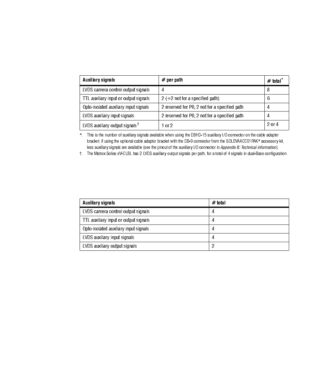
Matrox Solios eV-CLB and eV-CLBL in dual-Base configuration have
auxiliary/camera control signals in the following formats:
Matrox Solios eV-CLB and eV-CLBL, in single-Medium configuration, and
Matrox Solios eV-CLF and eV-CLFL have auxiliary/camera control signals in the
following formats:
When an auxiliary input signal is received in TTL format directly, it will be
clamped at a maximum of 5.7 V and at a minimum of -0.7 V to protect the input
buffer. Typically, the signal should have a maximum of 5 V and a minimum of
0 V. A signal over 2 V is considered high, while anything less than 0.8 V is
considered low.
The opto-isolated auxiliary input signals pass through an opto-coupler, a device
that protects the board from outside surges and different ground levels, and allows
the frame grabber to be totally isolated. The voltage difference across the positive
and negative components of the signal must be between 4.06 V and 9.165 V for
logic high, and between -5.0 V and 0.8V for logic low.
Auxiliar y signals # per path
# total
*
*. This is the number of auxiliary signals available when using the DBHD-15 auxiliary I/O connector on the cable adapter
bracket; if using the optional cable adapter bracket with the DB-9 connector from the SOLEVAACC01PAK* accessory kit,
less auxiliary signals are available (see the pinout of the auxiliary I/O connector in
Appendix B: Technical information
).
LVDS camera control output signals 4 8
TTL auxiliary input or output signals 2 (+2 not for a specified path) 6
Opto-isolated auxiliary input signals 2 reserved for P0, 2 not for a specified path 4
LVDS auxiliary input signals 2 reserved for P0, 2 not for a specified path 4
LVDS auxiliary output signals
†
†. The Matrox Solios eV-CLBL has 2 LVDS auxiliary output signals per path, for a total of 4 signals in dual-Base configuration.
1 or 2
2 or 4
Auxiliary signals # total
LVDS camera control output signals 4
TTL auxiliary input or output signals 4
Opto-isolated auxiliary input signals 4
LVD S aux iliary input signal s 4
LVDS auxiliary output signals 2