30 Chapter 2: Hardware installation
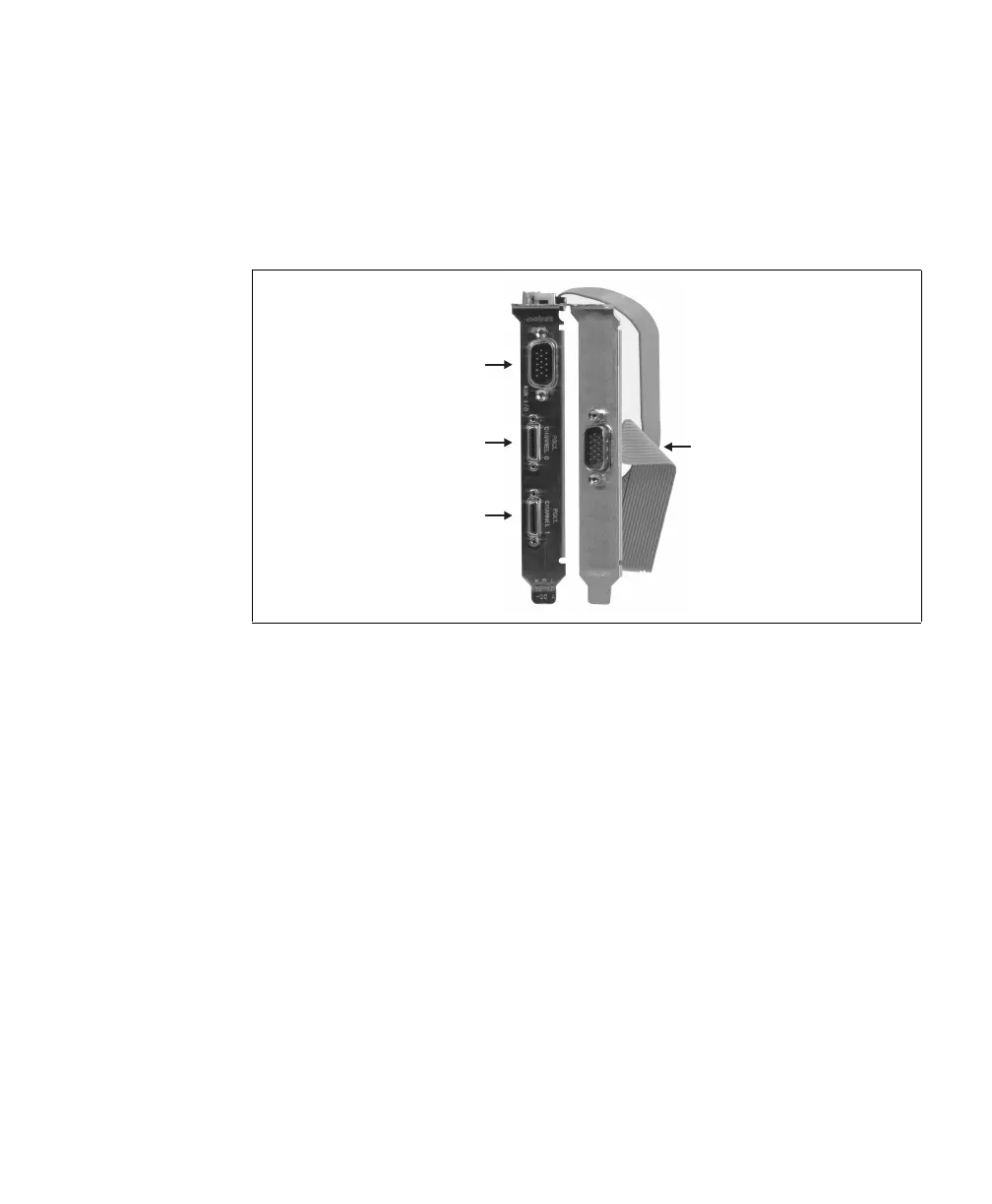
To access the signals of the internal auxiliary I/O connectors, you might have
installed the cable adapter bracket. It has the following connector:
• External auxiliary I/O connector 1 (DBHD-15 or DB-9). Used to
transmit/receive auxiliary signals for the other acquisition path.
To Matrox Solios eV-CLB in dual-Base configuration, you can connect two
independent video sources; one to each Camera Link connector. To Matrox Solios
eV-CLB in single-Medium configuration and to Matrox Solios eV-CLF, you can
only connect a single video source, regardless of the source’s configuration.
Warning Connecting a single-Medium video source to a board operating in dual-Base
configuration could seriously damage your video source. Note that for Matrox
Solios eV-CLB, the board is factory configured to operate in single-Medium
configuration.
To connect video sources to the Camera Link connectors, use standard Camera
Link cables with a 26-pin high-density male mini Camera Link connector (HDR
or SDR) at one end. For Matrox Solios eV-CLB, you should use PoCL-compliant
Camera Link cables (HDR or SDR) when connecting to PoCL-compliant video
sources. Camera Link cables are not available from Matrox; for possible sources,
see the Connectors on Matrox Solios eV-CLB and eV-CLF boards section in
Appendix B: Technical information.
uxiliary I/O
Connector 0
Camera Link
ideo Input
Connector 0
Camera Link
ideo Input
Connector 1
Auxiliary I/O
Connector 1