32 Chapter 2: Hardware installation
To Matrox Solios eV-CLBL in dual-Base configuration, you can connect two
independent video sources; one to each Camera Link connector. To Matrox Solios
eV-CLBL in single-Medium configuration and to Matrox Solios eV-CLFL, you
can only connect a single video source, regardless of the source’s configuration.
Warning Connecting a single-Medium video source to a board operating in dual-Base
configuration could seriously damage your video source. Note that for Matrox
Solios eV-CLBL, boards are all factory configured to operate in single-Medium
configuration.
To connect video sources to the Camera Link connectors, use standard Camera
Link cables with a 26-pin high-density male Camera Link connector (MDR) at
one end. For Matrox Solios eV-CLBL, you should use PoCL-compliant Camera
Link cables (MDR) when connecting to PoCL-compliant video sources. Camera
Link cables are not available from Matrox; for possible sources, see the Connectors
on Matrox Solios eV-CLB and eV-CLF boards section in Appendix B: Technical
information.
❖ If using both Camera Link connectors to connect to the same video source
(single-Medium or single-Full configuration), the cables you choose must be of
the same type and length. Otherwise, the cables can have different propagation
delays.
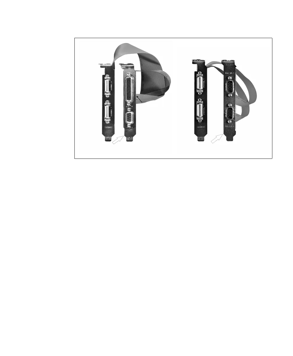
Camera Link
Video Input
Connector 0
Camera Link
Video Input
Connector 1
Auxiliary I/O
Connector 1
Auxiliary I/O
Connector 0
Cable Adapter Bracket with a
DBHD-44 and DB-9
Camera Link
Video Input
Connector 0
Camera Link
Video Input
Connector 1
Auxiliary I/O
Connector 0
Auxiliary I/O
Connector 1
Cable Adapter Bracket with
two DBHD-15 connectors