58 Chapter 4: Matrox Solios eV-CL hardware reference
To route a timer output on an auxiliary signal, use the MIL-Lite function
MdigControl() with M_IO_SOURCE
*
+ M_AUX_IOn (or + M_CC_IOn) set
to M_TIMERm. Set up the timers using MdigControl() with M_TIMER_....
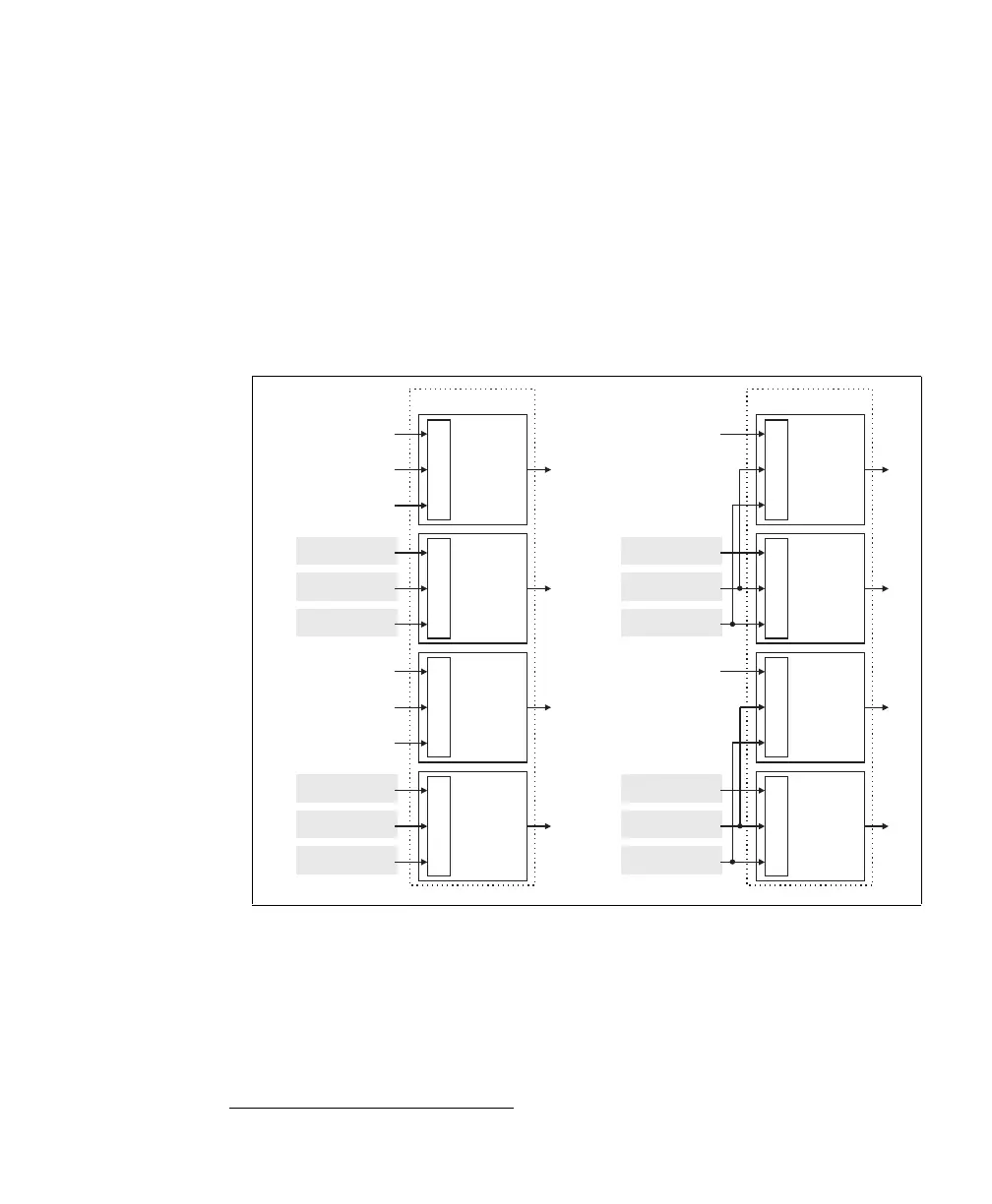
Trigger
The board accepts trigger input signals which allow, for example, image acquisition
to be synchronized with external events. Each PSG has 4 trigger controllers.
Multiple auxiliary signals can trigger a trigger controller; however, you can
program only one per trigger controller as a trigger input signal.
The trigger input signal must meet the specification of the auxiliary signal.
If using the trigger to start acquisition, the trigger signal’s pulse width must be
greater than two pixels; if using the trigger to start a timer, the trigger signal’s pulse
width must be greater than two clock periods of the timer. To determine the timer
*. As of MIL 10.
PSG 0 PSG 1
P0_TTL_AUX_IO_0
(M_AUX_IO8)
P0_OPTO_AUX_IN0
(M 6)_AUX_IO
P0_LVDS_AUX_IN0
(M 10)_AUX_IO
Trigger
Controller
0
MUX
P0_TTL_AUX_IO_1
(M 9)_AUX_IO
P0_OPTO_AUX_IN1
(M 7)_AUX_IO
P0_LVDS_AUX_IN1
(M 11)_AUX_IO
Trigger
Controller
1
MUX
TTL_AUX_IO_0
(M 2)_AUX_IO
OPTO_AUX_IN0
(M 0)_AUX_IO
LVDS_AUX_IN0
(M 4)_AUX_IO
Trigger
Controller
2
MUX
TTL_AUX_IO_1
(M 3)_AUX_IO
OPTO_AUX_IN1
(M 1)_AUX_IO
LVDS_AUX_IN1
(M 5)_AUX_IO
Trigger
Controller
3
MUX
P1_TTL_AUX_IO_0
(M 8)_AUX_IO
Trigger
Controller
0
MUX
P1_TTL_AUX_IO_1
(M 9)_AUX_IO
Trigger
Controller
1
MUX
TTL_AUX_IO_1
(M 3)_AUX_IO
Trigger
Controller
3
MUX
OPTO_AUX_IN1
(M 1)_AUX_IO
LVDS_AUX_IN1
(M 5)_AUX_IO
TTL_AUX_IO_0
(M 2)_AUX_IO
Trigger
Controller
2
MUX
OPTO_AUX_IN0
(M 0)_AUX_IO
LVDS_AUX_IN0
(M 4)_AUX_IO