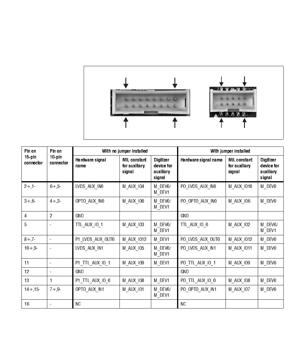
Connectors on Matrox Solios eV-CLB and eV-CLF boards 91
The pinout for these connectors are as follows. Refer to the description of external
auxiliary I/O connector 1 to establish if an auxiliary signal is specific to an
independent acquisition path and the type of signals that can be routed onto it.
16
15
2
1
10
9
2
1
Pin on
16-pin
connector
Pin on
10-pin
connector
With no jumper installed With jumper installed
Hardware signal
name
MIL constant
for auxiliary
signal
Digitizer
device for
auxiliary
signal
Hardware signal name MIL constant
for auxiliary
signal
Digitizer
device for
auxiliary
signal
2+,1- 6+,5- LVDS_AUX_IN0 M_AUX_IO4 M_DEV0/
M_DEV1
PO_LVDS_AUX_IN0 M_AUX_IO10 M_DEV0
3+,6- 4+,3- OPTO_AUX_IN0 M_AUX_IO0 M_DEV0/
M_DEV1
PO_OPTO_AUX_IN0 M_AUX_IO6 M_DEV0
42GND GND
5 - TTL_AUX_IO_1 M_AUX_IO3 M_DEV0/
M_DEV1
TTL_AUX_IO_0 M_AUX_IO2 M_DEV0/
M_DEV1
8+,7- - P1_LVDS_AUX_OUT0 M_AUX_IO12 M_DEV1 PO_LVDS_AUX_OUT0 M_AUX_IO12 M_DEV0
10+,9- - LVDS_AUX_IN1 M_AUX_IO5 M_DEV0/
M_DEV1
PO_LVDS_AUX_IN1 M_AUX_IO11 M_DEV0
11 - P1_TTL_AUX_IO_1 M_ AUX_IO9 M_DEV1 PO_TTL_AUX_IO_1 M_AUX_IO9 M_DEV0
12 - GND GND
13 1 P1_TTL_AUX_IO_0 M_AUX_IO8 M_DEV1 PO_TTL_AUX_IO_0 M_AUX_IO8 M_DEV0
14+,15- 7+,9- OPTO_AUX_IN1 M_AUX_IO1 M_DEV0/
M_DEV1
PO_OPTO_AUX_IN1 M_AUX_IO7 M_DEV0
16 - NC NC