10 Setting up the System
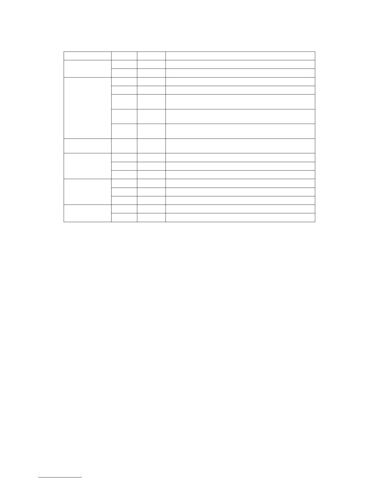
Descriptions of the front panel LEDs are listed in the following table.
Table 2. Description of Front Panel LEDs
LED Name Color Condition Description
Power/Sleep LED Green ON Power On
OFF Off
Status Green ON System Ready
Green BLINK System ready, but degraded: some CPU fault, DIMM killed
Amber ON Critical alarm: Critical power module failure, critical fan
failure, voltage (power supply), voltage and thermal fault
Amber BLINK Non-critical failure: Redundant fan failure, redundant power
failure, non-critical power and voltage
OFF AC power off; powered down (DC-off state or S5), and no
degraded, non-critical, critical conditions exist*
Hard Drive
Activity
Green BLINK Hard drive activity
NIC 1 Activity Green ON Linked
Green BLINK LAN activity
OFF Idle
NIC 2 Activity Green ON Linked
Green BLINK LAN activity
OFF Idle
ID LED (rack
only)
Blue BLINK Server identification; Toggled by ID button or software
OFF Server identification; Toggled by ID button or software
* When the server is powered down (transitions to the DC-off state or S5), the BMC is still on
standby power and retains the sensor and front panel status LED state established before the
power-down event. If the system status is normal when the system is powered down (the
LED is in a solid green state), the system status LED will be off.