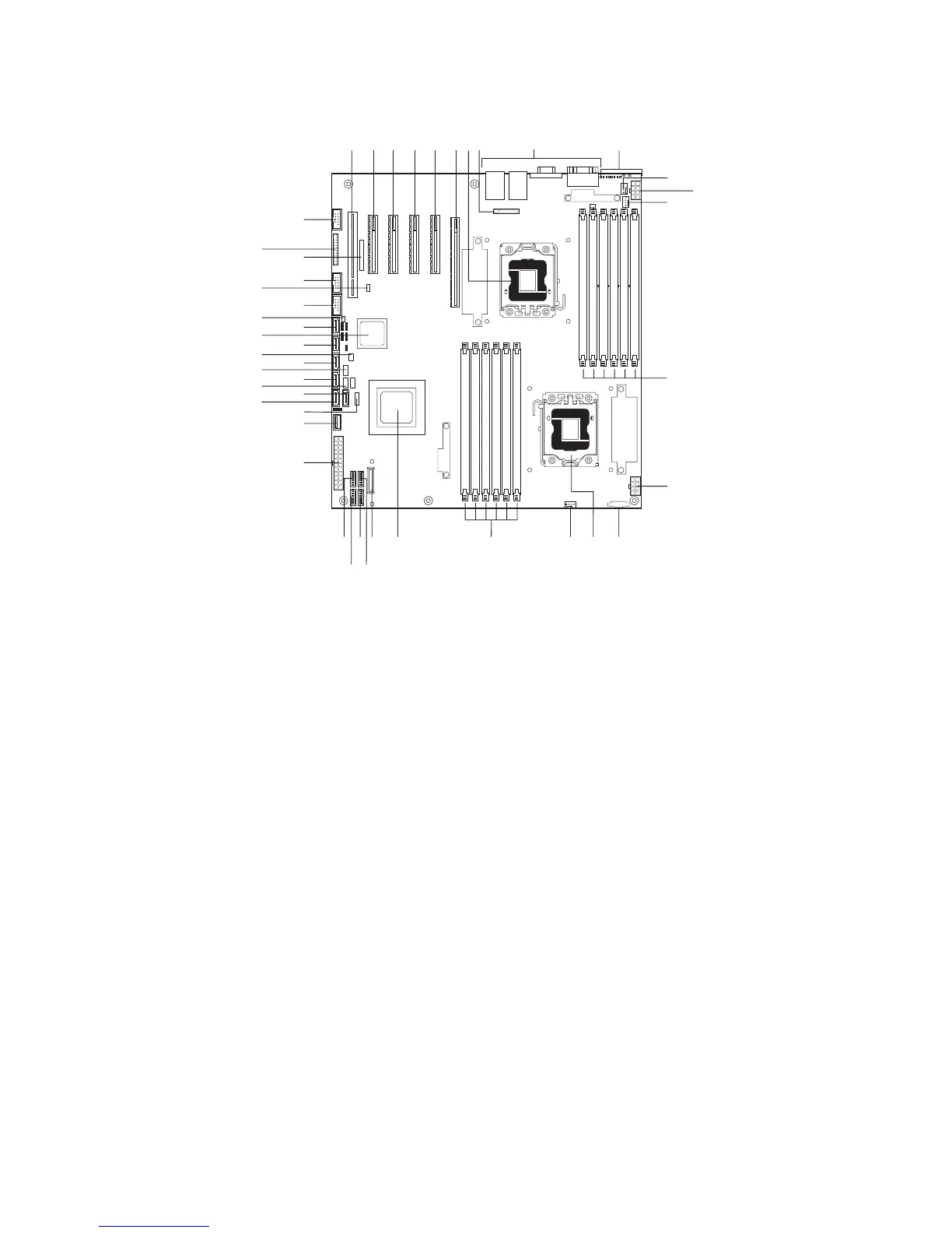
Connector and Header Locations
Figure 20. Server Board Connector and Component Locations
A. Slot 1 (PCI, 32-bit, 33 MHz) P. Aux Power Signal EE. HSBP B
B. Slot 2 (PCIe x4) Q. CPU 2 Socket FF. SATA 2
C. Slot 3 (PCIe2 x8) R. CPU 2 Fan GG. HSBP A
D. Slot 4 (PCIe2 x8) S. DIMM Sockets (CPU 2;
see figure 23)
HH. SATA 3
E. Slot 5 (PCIe2 x8) T. IOH II. SATA RAID 5 Key
F. Slot 6 (PCIe2 x8) U. SAS Module Slot JJ. SATA 4
G. CPU 1 Socket V. System Fan 3 KK. ICH10
H. CMOS Battery W. System Fan 4 LL. SATA 5
I. I/O Ports (see page 8, figure 1) X. System Fan 2 MM. HDD Activity LED
J. Diagnostic LEDs (see page 27,
figure 22)
Y. System Fan 1 NN. USB
K. System Fan 5 Z. Main Power OO. USB SSD
L. CPU 1 Power AA. Type A USB Port PP. USB
M. CPU 1 Fan BB. LCP/IPMB Header QQ. RMM3 Slot
N. DIMM Sockets (CPU 1;
see figure 23)
CC. SATA 1 RR. Front Panel Header
O. CPU 2 Power DD. SATA 0 SS. Serial Port B