Detailed Description
Default Register Setting
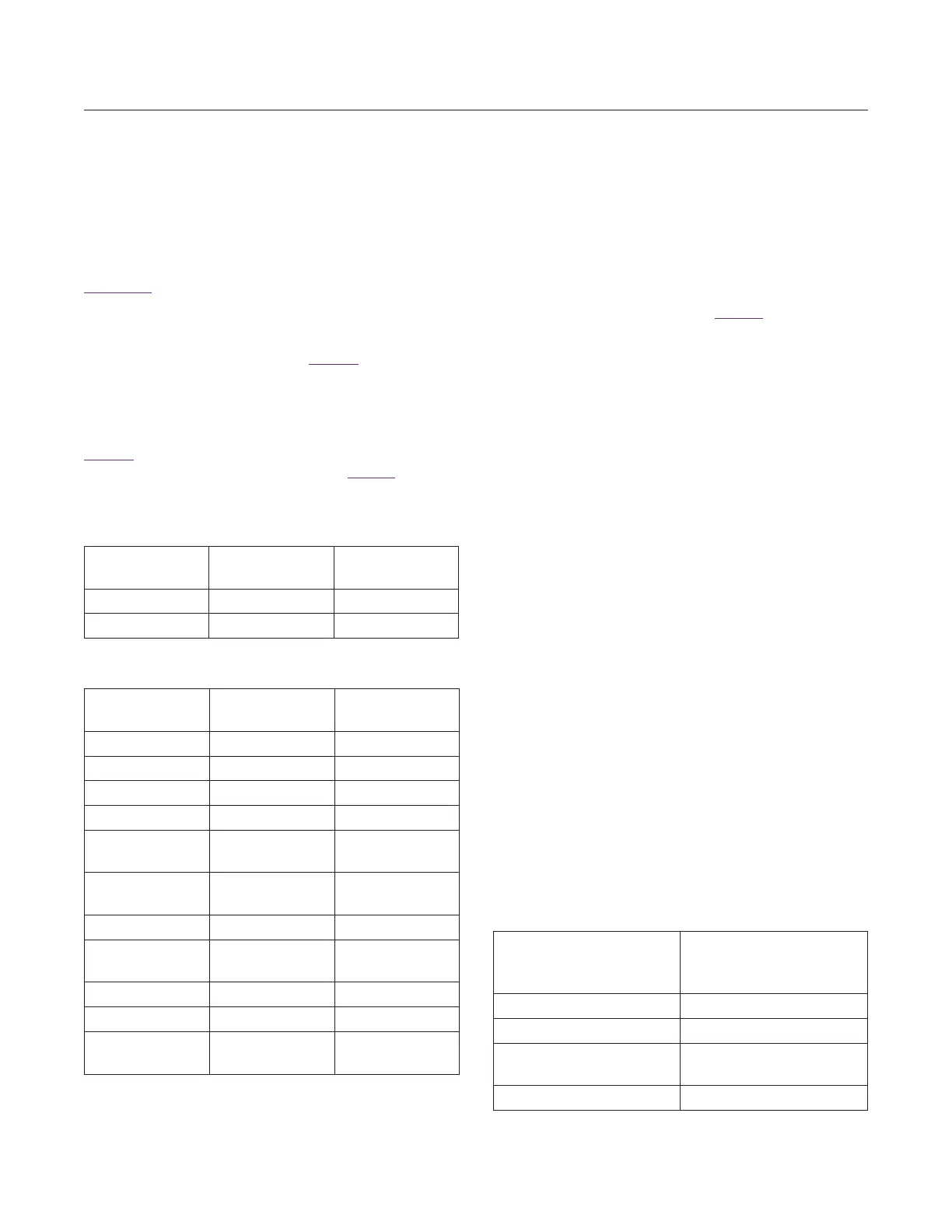
The registers will contain the reset values specified in the
Registers section of the data sheet upon power-up. It is
necessary for certain bit fields in particular registers to
be programmed with fixed values that are different from
the power-on reset values. These register bit fields and
the required values are given in Table 1. These values
must be programmed whenever the IC is power-cycled.
Note that these bits are described as “Reserved" in the
datasheet. Nevertheless, for these reserved bits alone,
the values indicated must be programmed.
Table 2 includes the default register bit values with the
above specified bits programmed, as in Table 1.
Low-Noise Amplier (LNA)
The MAX2771 integrates two low-noise amplifiers, one for
the L1 band (high band) and the other for the L2/L5 band
(low band). Both inputs require AC coupling capactors.
Bits LNAMODE in the Configuration 1 register control
the modes of the two LNAs. See Table 3. The high-band
LNA input impedance is matched to 50Ω at a frequency
of 1575MHz, providing the specified high-band external
matching circuit is used. The low-band LNA input imped-
ance is matched to 50Ω at a frequency of 1227MHz,
providing the specified low-band external matching circuit
is used.
The output of each LNA is brought out to a separate pin.
The output impedance of the high-band LNA is matched
to 50Ω at frequency of 1575MHz, and the low-band LNA
input impedance is matched to 50Ω at a frequency of
1227MHz.
Mixer
The MAX2771 includes a quadrature mixer to output low-
IF, or zero-IF, I and Q signals. There are two inputs to
the mixer; one for high-band and the other for low-band.
The high-band mixer input impedance is matched to 50Ω
at a frequency of 1575MHz, while the low-band mixer
input impedance is matched to 50Ω at a frequency of
1227MHz. The quadrature mixer requires a low-side LO
injection. The output of the LNA and the input of the mixer
are brought off-chip to facilitate the use of a SAW filter. On
the MAX2771, the RF signal has been made accessible
between the first LNA stage output and mixer input. If
filtering is not desired, these pins can be connected
through a coupling capacitor. However, filtering introduced
at this point has minimal effect on the excellent sensitivity
of the receiver. For example, for typical device parameters,
a SAW filter with 1dB insertion loss would degrade
cascaded NF (and therefore receiver sensitivity) by only
about 0.15dB. While no external filtering is required for
Table 1. Required Register Bit Field
Values
Table 2. Default Register Setting
Table 3. LNA Selection
REGISTER
ADDRESS
BIT
RANGE
BINARY
VALUE
0x0 29:22 11111010
0x9 24:22 011
REGISTER
NAME
ADDRESS DEFAULT
Conguration 1 0x0 0xBEA41603
Conguration 2 0x1 0x20550288
Conguration 3 0x2 0x0EAFA1DC
PLL Conguration 0x3 0x698C0008
PLL Integer
Division Ratio
0x4 0x00C00080
PLL Fractional
Division Ratio
0x5 0x08000070
DSP Interface 0x6 0x08000000
Clock
Conguration 1
0x7 0x010061B2
Test Mode 1 0x8 0x01E0F401
Test Mode 2 0x9 0x00C00002
Clock
Conguration 2
0xA 0x010061B0
LNA MODE
(CONFIGURATION 1
REGISTER)
MODE
00 LNA_HI is active
01 LNA_LO is active
10
Both LNA_HI and
LNA_LO are o
11 RESERVED
www.maximintegrated.com
Maxim Integrated
│
17
MAX2771 Multiband Universal GNSS Receiver