ADC
The MAX2771 features an on-chip ADC to digitize the
down-converted GNSS signal. The ADC supports the
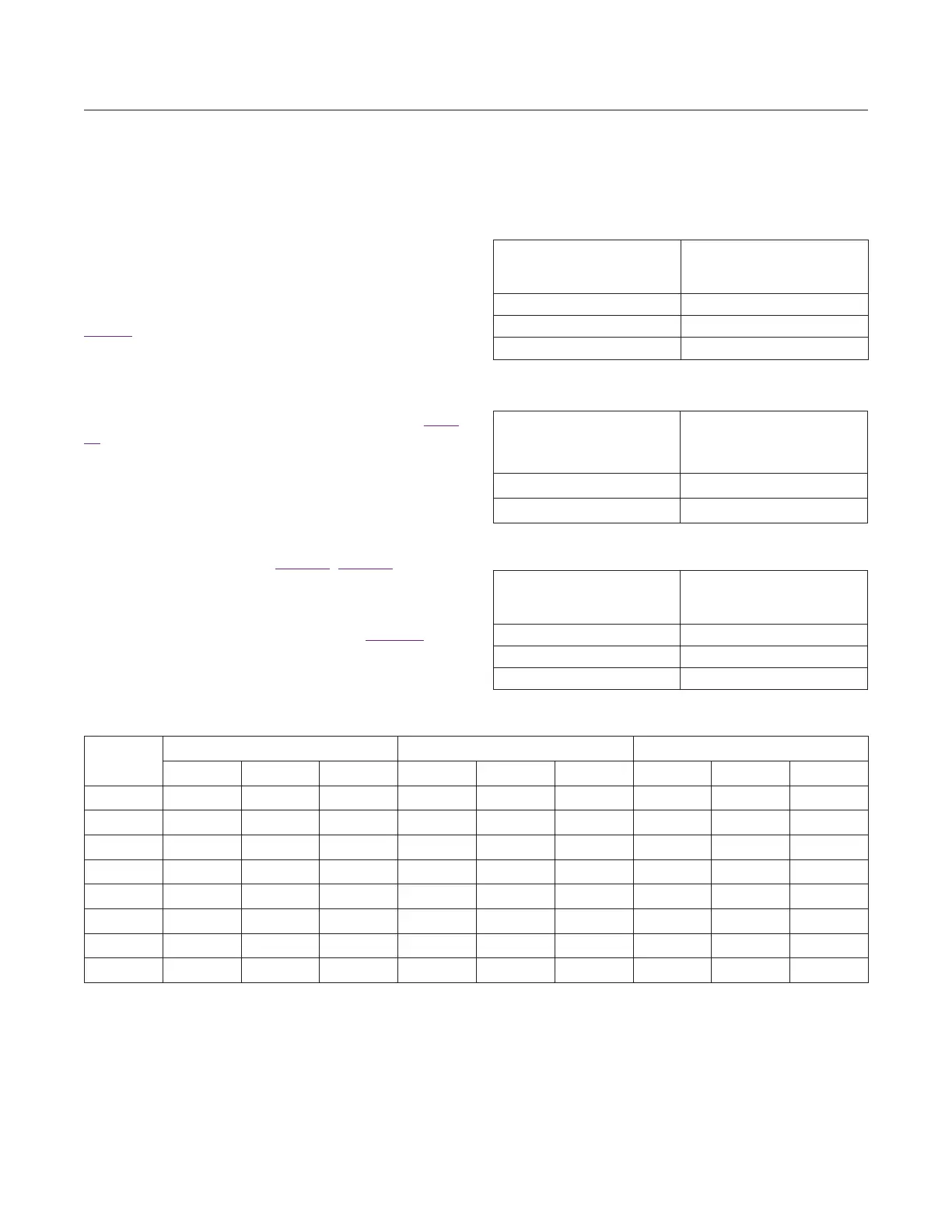
digital output in three different formats: unsigned binary,
sign and magnitude, or two’s complement format by set-
ting the FORMAT bits in Configuration 2 register. Refer to
Table 9. The sampled output is provided in a 2-bit format
(1-bit magnitude and 1-bit sign) by default, and also can
be configured as 1-bit or 2-bit in both I and Q channels,
or 1-bit, 2-bit, or 3-bit in the I channel only. If only the
I channel is used, the Q channel can be disabled with
the IQEN bits in the Configuration 2 register. See Table
10. MSB bits are output on the I1 or Q1 pins and LSB
bits are output on the I0 or Q0 pins, for I or Q channel,
respectively. In the case of 3-bit output data format, the
MSB is output on I1, the second bit is on I0, and the LSB
is on Q1. The Q ADC must be enabled in 3-bit output data
mode by setting the IQEN bit to 1. The number of bits of
the ADC can be configured through the BITS field in the
Configuration 2 register. See Table 11. Figure 1 illustrates
the ADC quantization levels for 2-bit and 3-bit cases and
also describes the sign/magnitude data mapping. The
variable T = 1 designates the location of the magnitude
threshold for the 2-bit case. Also refer to Table 12. The
maximum ADC sampling rate is 44MHz.
Table 9. ADC Output Data Format Settings
Table 10. IQ Channels Enable Settings
Table 11. ADC Output Bits Setting
Table 12. Output Data Format
FORMAT
(CONFIGURATION 2
REGISTER)
ADC OUTPUT DATA
FORMAT
00 Unsigned Binary
01 Sign and Magnitude
1X Two’s Complement Binary
IQEN
(CONFIGURATION 2
REGISTER)
ENABLED CHANNEL
0 I channel only
1 Both I and Q channels
BITS
(CONFIGURATION 2
REGISTER)
NUMBER OF BITS
IN THE ADC
000 1 bit
010 2 bits
100 3 bits
INTEGER
VALUE
SIGN/MAGNITUDE UNSIGNED BINARY TWO’S COMPLEMENT BINARY
1b 2b 3b 1b 2b 3b 1b 2b 3b
7 0 01 011 1 11 111 0 01 011
5 0 01 010 1 11 110 0 01 010
3 0 00 001 1 10 101 0 00 001
1 0 00 000 1 10 110 0 00 000
-1 1 10 100 0 01 011 1 11 111
-3 1 10 101 0 01 010 1 11 110
-5 1 11 110 0 00 001 1 10 101
-7 1 11 111 0 00 000 1 10 100
www.maximintegrated.com
Maxim Integrated
│
20
MAX2771 Multiband Universal GNSS Receiver