Product description
0000000141 - 002 - EN 12
Active leaks can lead to serious accidents resulting in death.
Assess the risk for the equipment in the risk assessment.
3 Product description
3.1 Design and function
Structure
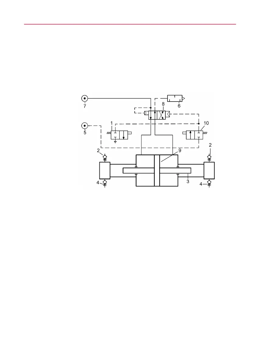
Fig. 3-1 Schematic circuit diagram of the double-acting gas booster
Function description
The operating principle of a gas booster is similar to the one of a pressure inten-
sifier. Low pressure is applied to the large area of the air piston (9) which applies
high force to the small area of the high pressure piston (3).
The piston of the gas booster carries out oscillating movements until the stall
pressure is reached. In doing so, the high pressure piston induces and compress-
es the compressed fluid by means of the check valves into the gas inlet (2) and
gas outlet (4). The outlet pressure results from the set drive pressure, primary
pressure and volume flow.
The continuous supply is achieved by means of an internally controlled direction-
al valve, the spool valve (8). The spool valve alternately guides the drive fluid to
the two sides of the air piston. The spool valve is controlled via two directional
1 Pilot valve lower cap
2 Gas inlet (A)
3 High pressure piston
4 Gas outlet (B)
5 Control air port (X)
6 Exhaust port
7 Drive air inlet (pL)
8 Control slide valve
9 Air piston
10 Pilot valve top cap