Installation
27 0000000141 - 002 - EN
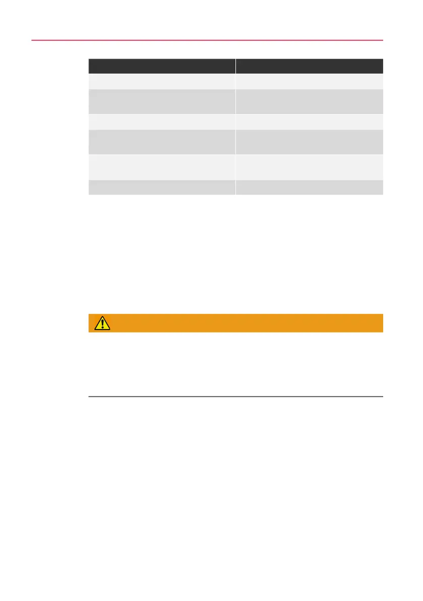
Tab. 5-2 Calculation of the stall pressure
Legend:
p
L
= drive pressure
p
B
= operating pressure
p
A
= primary gas pressure
i = pressure ratio
i
1
= pressure ratio stage 1
i
2
= pressure ratio stage 2
5.4.2 Commissioning
WARNING
Risk of injury due to extreme temperatures!
The surfaces of the product can be very hot or very cold. This can lead to acci-
dents resulting in severe injuries or death.
► Before working on the product, please ensure that the product is at ambient
temperature.
Details about the commissioning of the gas booster are described below:
1) Check all connections for proper installation.
2) Check all connecting lines for mechanical damage.
3) Slowly open the supply line.
– The compressed fluid flows in.
4) If applicable, open the control air line.
5) Slowly open the compressed air line of the compressed air line system to the
gas booster.
– The gas booster automatically starts to compress the gas.
Gas booster design Standstill pressure
Single-stage, single-acting p
B
= p
L
* i
Single-stage, double-acting / quadru-
ple-acting
p
B
= i * p
L
+ p
A
Two-stage p
B
= i
2
* p
L
+ i
2
/ i
1
* p
A
Single-stage, single-acting with two
drive parts
p
B
= p
L
* i
Single-stage, double-acting / quadru-
ple-acting with two drive units
p
B
= i * p
L
+ p
A
Two-stage with two / three drive units p
B
= i
2
* p
L
+ i
2
/ i
1
* p
A