Installation
0000000141 - 002 - EN 24
5.2 Gas booster installation
WARNING
Risk of injury posed by improper installation of the gas booster!
Improper installation of the gas booster can lead to accidents resulting in severe
injuries or death.
► Permissible pressures at the inlet and outlet of the gas booster must not ex-
ceed the maximum permitted operating pressure of the gas booster.
► In case of two-stage gas boosters, the maximum permitted operating pres-
sure of the first and second stage may be different.
The product is enclosed in dust-protection packaging. Do not remove this pack-
aging until shortly before installation. Dispose of this packaging in an environ-
mentally friendly manner.
Attach the gas booster using the fastening holes provided using screws or bolts
with a strength of at least 4.6. Determine the adequate screw or bolt size using
the enclosed general drawing.
The preferred installation position is vertical.
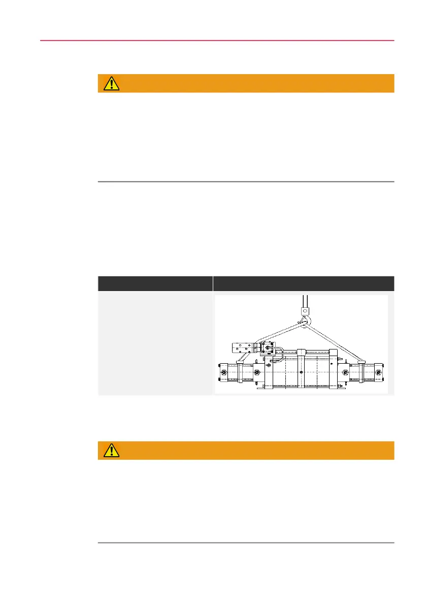
Tab. 5-1 Lifting points double-acting DLEs
5.3 Installation of connecting lines
WARNING
Risk of injury posed by improper installation of the connecting lines!
Improper installation of the gas booster can lead to accidents resulting in severe
injuries or death.
► Connecting lines must be hermetically sealed long-term.
► Check connecting lines for leaks.
► Replace any faulty components immediately.
Lifting points
All double-acting gas boost-
ers can be attached with 2
belt straps.