Use in explosion-prone zones
0000000141 - 002 - EN 46
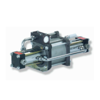
Purging plan for single-stage, single-acting and two-stage, double-acting gas
boosters
1) Prior to commissioning the gas booster, connect nitrogen to the inlet pres-
sure port (A) and to the purge port (SFP).
2) Switch on the gas booster for approx. 1 minute (based on the volume to be
purged).
3) Switch off the gas booster after the purging process has been completed.
4) The inlet pressure line (A) may then be connected with the gas source. Con-
tinuously purge the purge port during the compression process.
5) After the compression process has been completed, purge the compression
chamber again as described in step 2.
Volume flow for gas purging processes
To ensure an adequate purging performance, different volume flows must be en-
sured depending on the gas booster. The minimum required volume flow is
shown in the table below.
Tab. 10-2 Volume flows
Type Volume flow l
N
/
min
Type Volume flow l
N
/
min
DLE 2-1 190 DLE 15-1-2 30
DLE 5-1 90 DLE 30-1-2 20
DLE 15-1 40 DLE 75-1-2 10
DLE 30-1 20 DLE 2-2* 170
DLE 75-1 10 DLE 5-2* 80
DLE 2* 170 DLE 15-2* 30
DLE 5* 90 DLE 30-2* 20
DLE 15* 30 DLE 75-2* 10
DLE 30* 20 DLE 2-5-2 100
DLE 75* 10 DLE 5-15-2 60
DLE 2-5 110 DLE 5-30-2 70
DLE 5-15 60 DLE 15-30-2 20
DLE 5-30 70 DLE 15-75-2 20
DLE 15-30 20 DLE 30-75-2 10
DLE 15-75 30 DLE 30-75-3 10
DLE 30-75 10 8 DLE 1,65 -**
DLE 2-1-2 190 8 DLE 3 -**
DLE 5-1-2 90 8 DLE 6 -**