10
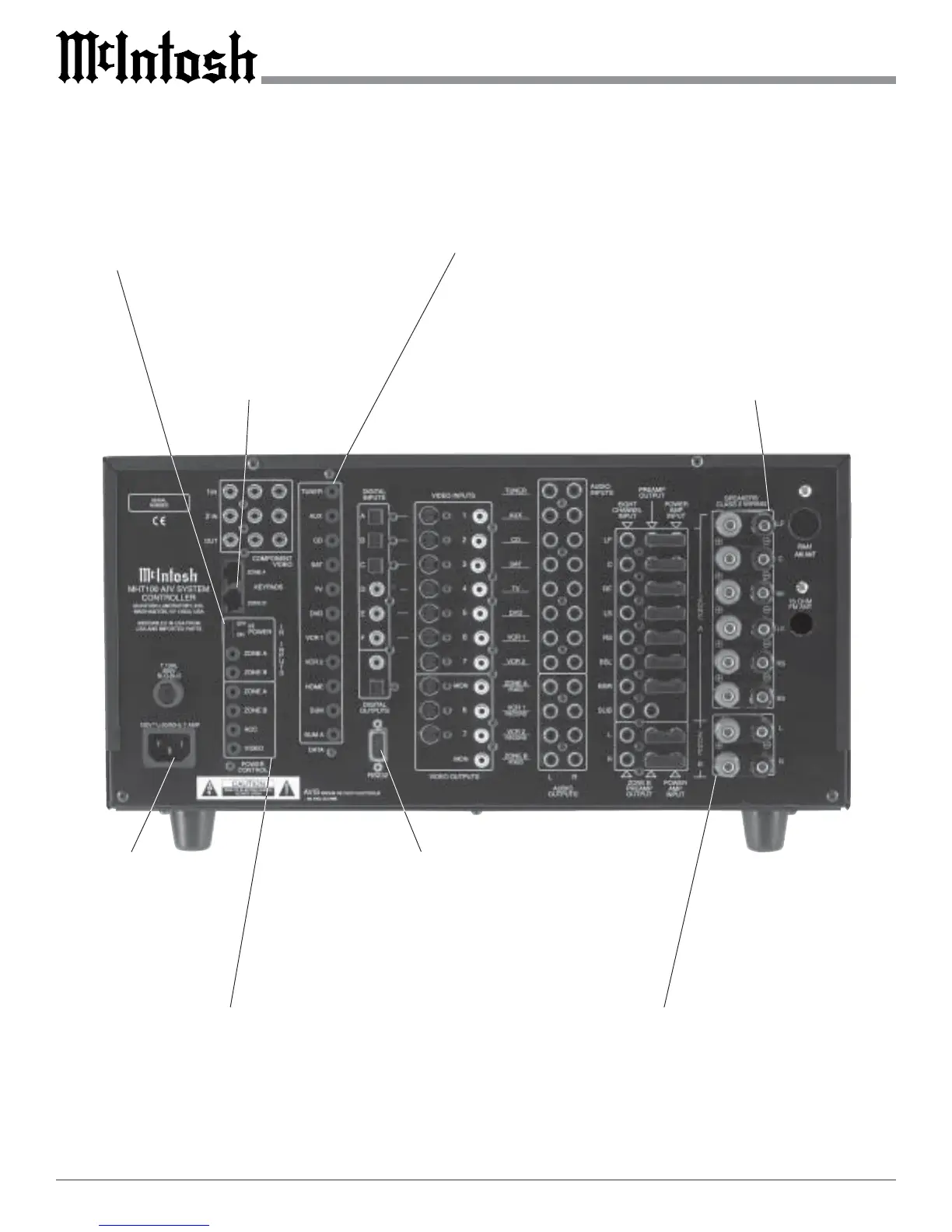
Rear Panel Switch, Loudspeaker and Control Connections
Connect the MHT100
power cord to a live
AC outlet. Refer to in-
formation on the back
panel to determine the
correct voltage
POWER CONTROL A and B send a turn
On/Off signal to a McIntosh Power Ampli-
fier for both Areas. The ACC POWER
CONTROL sends a turn On/Off signal to
McIntosh Source Components. The VIDEO
POWER CONTROL sends a turn On/Off
signal to McIntosh Video Source Compo-
nents
DATA PORTs send signals to compatible source com-
ponents to allow remote control operation. The SUM
Data Port for Zones A and B connects to other McIn-
tosh Components. The HOME Data Port connects to
an optional Home Controller
RS232 connector
for connection to a
computer or other
control device
IR INPUTS for
Zone A or B ex-
ternal Sensors. IR
POWER On/Off
Switch for Zone A
or B external Sen-
sors
KEYPADS
ZONE A and B
for a McIntosh
Keypad or IR
room sensor
Connections for Zone A Loud-
speakers; which includes the Left,
Center and Right Front Channels.
There are also connections for the
Left, Back and Right Surround
Loudspeakers
Connections for Zone B Loudspeakers,
Left and Right

 Loading...