35
Digital Input
There are three Optical Digital Inputs and three Coaxial
Digital Inputs available for assignment with any of the
seven Analog Audio Inputs. The following example de-
scribes how to reassign Digital Input A, which by default
has been assigned to AUX Input, over to the VCR2 Input
instead.
8. Using the Up or Down directional push-buttons
select Number 1 SOURCE INPUT from the On-Screen
Menu, followed by pressing the Left or Right di-
rectional push-buttons to select the AUX Input, Num-
ber 1. Refer to figure 24.
9. Using the Up or Down directional push-buttons
select DIGITAL INPUT on the On-Screen Menu, fol-
lowed by pressing the Left or Right directional
push-buttons to select OFF.
Note: The default setting for the AUX Digital Input is
OPTical A.
10. Using the Up or Down directional push-buttons
select Number 1 SOURCE INPUT from the On-Screen
Menu, followed by pressing the Left or Right di-
rectional push-buttons to select the VCR2 Input.
11. Using the Up or Down directional push-buttons
select DIGITAL INPUT on the On-Screen Menu, fol-
lowed by pressing the Left or Right directional
push-buttons to select
OPTical A.
Note: The default
setting for the
VCR2 Digital
Input is OFF.
Input Trim
Analog Audio Source
components can have
slightly different volume
levels. This could result in
the constant need to read-
just the MHT100 Volume
Control when switching between different Program
Sources. A volume trim feature on the MHT100 allows you
to adjust or trim the levels of the various inputs so that they
have the same relative volume. The Default Trim Setting
for all Inputs is 0dB and each input has a range of adjust-
ment in Trim Volume Level from +3dB to -6dB. The Tuner
is a frequently listened to source and makes a good refer-
ence for comparing the volume between different inputs. It
is helpful to note first, before beginning the adjustments,
which inputs have volume levels that are louder or quieter
than the Tuner Input. In the example below, the audio from
the AUX Input Source is louder than the sound from the
Tuner Input:
Note: The Input Trim Level Adjustment only affects Audio
Source Components connected to the Left and Right
Analog Inputs. There is no effect on the volume levels
from Digital Audio Sources Components connected to
one of the Digital Inputs. The Record Output Levels are
unaffected by any changes in the Input Trim Setting.
12. Using the Up or Down directional push-buttons
select Number 1 SOURCE INPUT from the On-Screen
Menu, followed by pressing the Left or Right di-
rectional push-buttons to select the AUX Input, Num-
ber 1. Refer to figure 24.
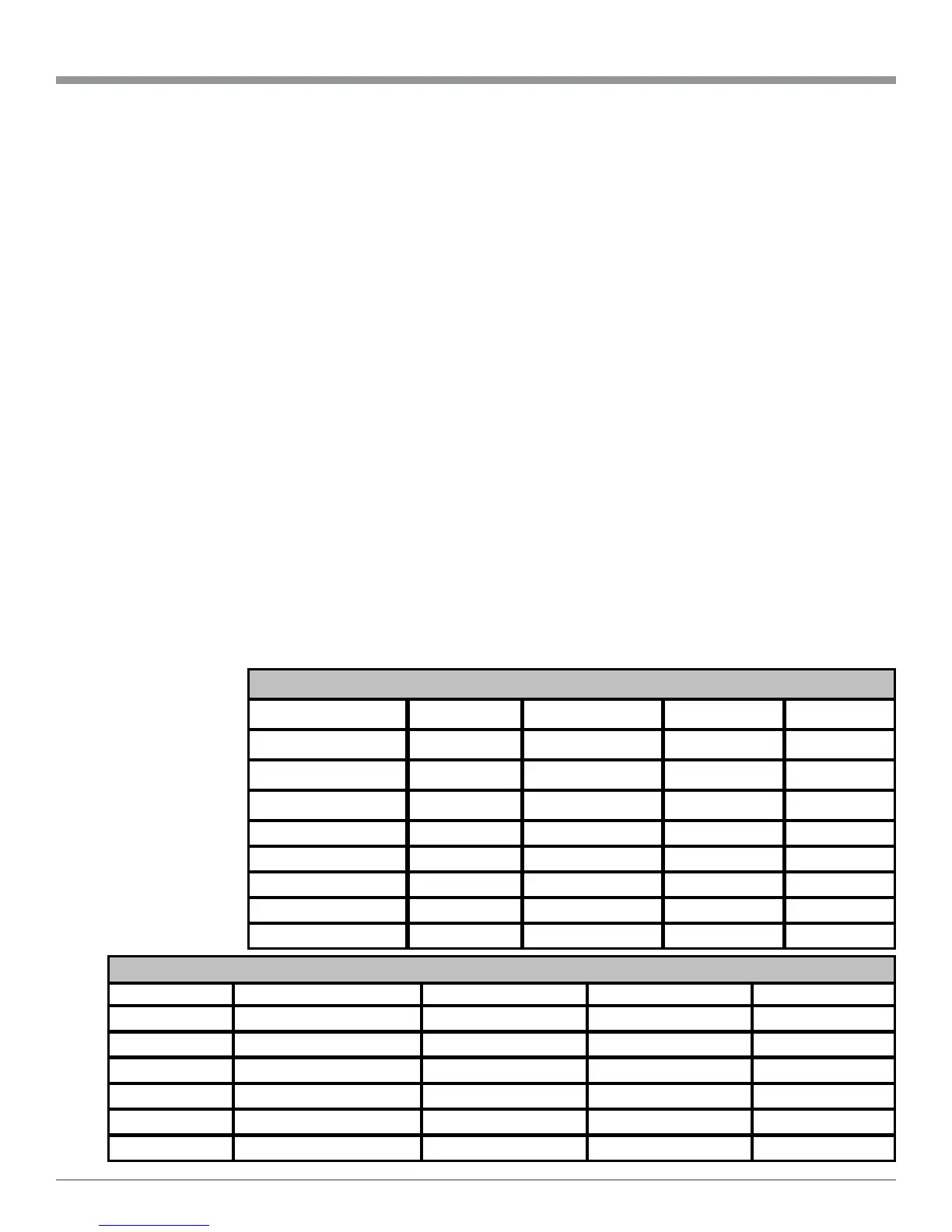
SETUP, con’t
S ource Num be r De fa ult Title Ne w Title De fa ult Tri m Ne w Trim
1 AU X 0dB
2 CD 0dB
3 SAT 0dB
4 TV 0dB
5 DV D 0dB
6 VCR 1 0dB
7 VCR 2 0dB
8 TU NER 0dB
Analog Audio and Video Inputs Source Settings
Source Letter Default Input Number Default Input Name Ne w Input Number New Input Name
A(Optical) 1 AUX
B(Optical) 2 CD
C(Optical) 3 SAT
D(Coaxial) 4 TV
E(Coaxial) 5 DVD
F(Coaxial) 6 VCR 1
Digital Audio Source Settings

 Loading...