6
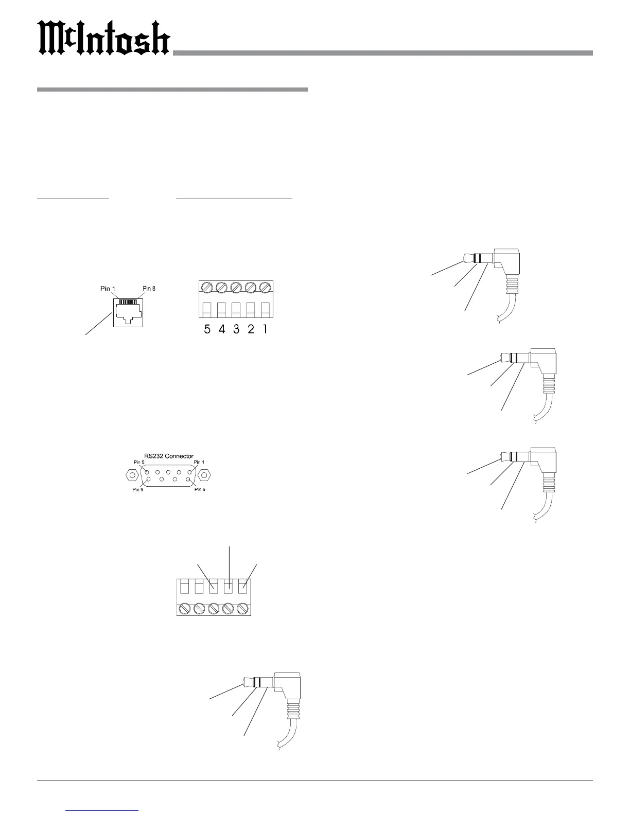
Connector Information
Keypad Terminal Connector
To use a WK-3 or WK-4 keypad with the MHT100, con-
nect the shield and four leads of a shielded 4 conductor
cable to a RJ-45 Connector Plug, according to the numbers
listed below. There is a numbered connector built-in to
each keypad, which has a different pin out.
MHT100 RJ-45 WK-3 and WK-4 Keypad
1. Signal Data 1. Supply Voltage Positive
2. Signal Data Gnd. 2. Supply Voltage Negative
and Cable Shield 3. Cable Shield
3. N/C 4. Signal Data
4. Supply Voltage Negative 5. Signal Data Gnd.
5. Supply Voltage Positive
6. N/C
7. N/C
8. N/C
RS232 DB9 Connector Pin Layout
1. N/C 6. N/C
2. Data Out (TXD) 7. N/C
3. Data In (RXD) 8. N/C
4. N/C 9. N/C
5. Gnd.
RAA1 Connector
Connect the shield and two leads of a shielded 2 conductor
cable to the supplied 5 Pin
Terminal Connector Plug.
Refer to the connection infor-
mation on the top cover of
the RAA1.
Power Control Connector
The MHT100’s Power Control Outputs provide a 12 volt
signal. Use a 1/8 inch stereo
mini phone plug to connect
to the Power Control Input.
Data and IR Port Connectors
The MHT100’s Data Port Output provides Remote Control
Signals and the IR Port allows for the connection of other
brands IR Sensors. Use a 1/8 inch stereo mini phone plug
to connect to the Data Port Inputs on McIntosh Source
Units.
Note: The MHT100 Rear Panel IR POWER Switch setting
determines if twelve volt is present at the Zone A and B
IR INPUTS.
MHT100 Keypad Socket
Red (TV)
Black (RF)
Green (GND)
Positive
N/C
Ground
Data Signal
N/C
Data Ground
Data Port Connector
IR Port Connector
with Rear Panel IR
Power Switch Set
to On
Data Signal
Ground
+12Volts
Data Signal
Ground
IR Port Connector
with Rear Panel IR
Power Switch Set
to Off
N/C
 Loading...