1-8
REFRIGERANT PIPING
Allowable Piping Length
If the pipe is too long, both the capacity and reliability of
the unit will drop. As the number of bends increases,
resistance to the fl ow of refrigerant system increases, thus
lowering cooling capacity. As a result, the compressor
may become defective. Always choose the shortest path
and follow the recommendations as tabulated below:
Model
Min. Allowable Length, m
Max. Allowable Length, m
Additional charge of refrigerant
Max. Allowable Elevation, m
Gas Pipe Size, mm/(in)
Liquid Pipe Size
, mm/(in)
10 15
3
15
20
10
9.52 (3/8")
6.35 (1/4")
*Be sure to add the proper amount of additional refrigerant.
Failure to do so may result in reduced performance.
Remark: The refrigerant pre-charged in the outdoor
unit is for piping length up to 7.5m.
Piping Works and Flaring technique
• Do not use contaminated or damaged copper tubing. If
any piping, evaporator or condenser had been exposed
or had been opened for 15 seconds or more, the system
must be vacuumed. Generally do not remove plastic,
rubber plugs and brass nuts from the valves, fi ttings,
tubing and coils until it is ready to connect suction or
liquid line into valves or fi ttings.
• If any brazing work is required, ensure that nitrogen
gas is passed through coil and joints while the brazing
work is being done. This will eliminate soot formation
on the inside wall of copper tubings.
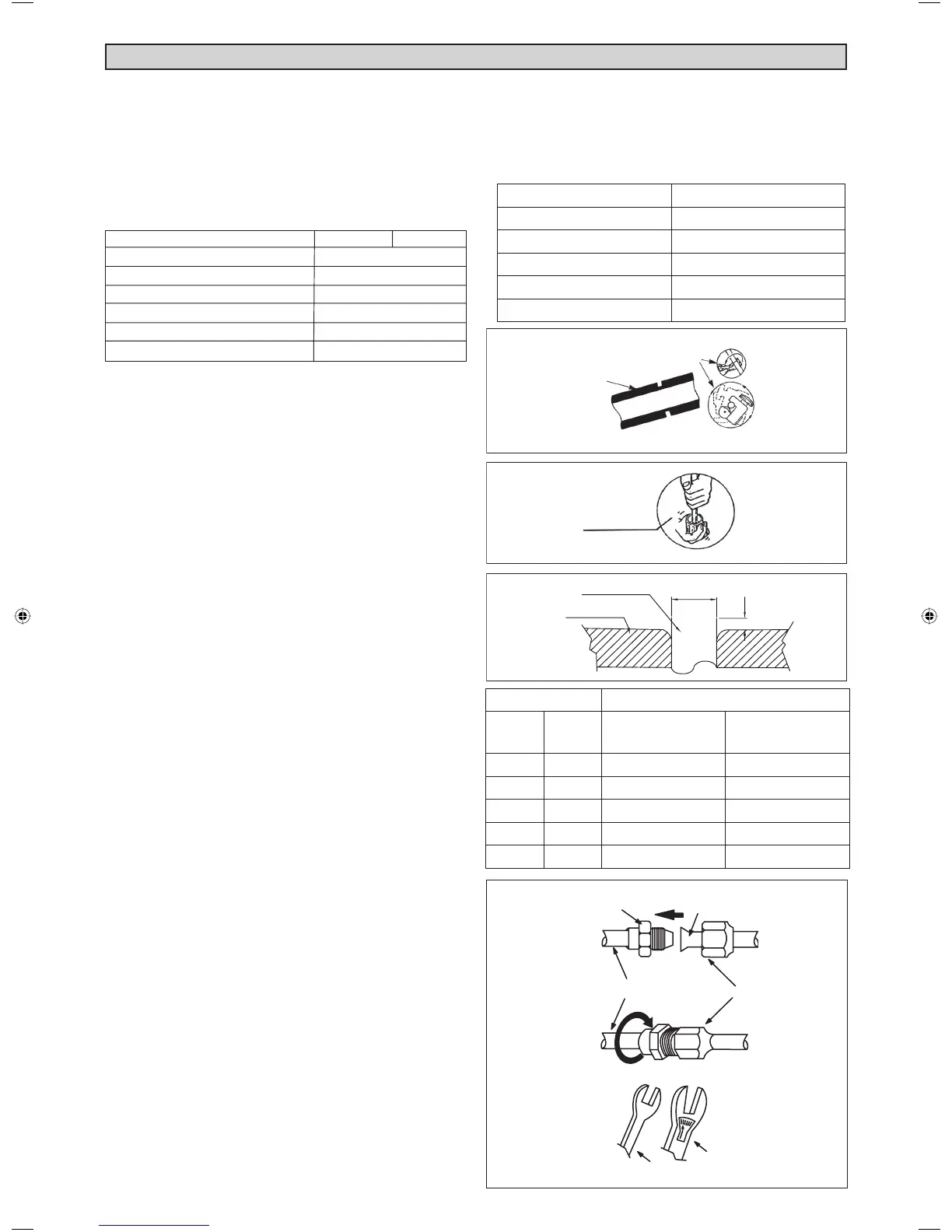
• Cut the pipe stages by stages, advancing the blade of
pipe cutter slowly. Extra force and a deep cut will cause
more distortion of pipe and therefore extra burr. See
Figure A.
• Remove burrs from cut edges of the pipes with remover.
See Figure B. Hold the pipe on top position and burr
removel at lower position to prevent metal chips from
entering the pipe. This will avoid unevenness on the
fl are faces which will cause gas leak.
• Insert the fl are nuts, mounted on the connection parts
of both the indoor unit and outdoor unit, into the copper
pipes.
• The exact length of pipe protruding from the top surface
of the swaging block is determined by the fl aring tool.
See Figure C.
• Fix the pipe fi rmly on the swaging block. Match the
centers of both the swaging block and the fl aring punch,
then tighten the fl aring punch fully.
• The refrigerant pipe connection are insulated by closed
cell polyurethane.
Piping Connection To The Units
• Align the center of the piping and tighten the fl are nut
suffi ciently with fi ngers. See Figure D.
• Finally, tighten the fl are nut with torque wrench until the
wrench clicks.
• When tightening the fl are nut with the torque wrench,
ensure that the tightening direction follows the arrow
indicated on the wrench.
• The refrigerant pipe connection are insulated by closed
cell polyurethane.
Pipe Size, mm (in) Torque, Nm / (ft-Ib)
6.35 (1/4") 18 (13.3)
9.52 (3/8") 42 (31.0)
12.70 (1/2") 55 (40.6)
15.88 (5/8") 65 (48.0)
19.05 (3/4") 78 (57.6)
Ø Tube, D A (mm)
Inch mm Imperial
(Wing-nut Type)
Rigid
(Clutch Type)
1/4" 6.35 1.3 0.7
3/8" 9.52 1.6 1.0
1/2" 12.70 1.9 1.3
5/8" 15.88 2.2 1.7
3/4" 19.05 2.5 2.0
Figure A
Figure B
Figure C
Figure D
Flared Tube
Flare Joint
Flare Nut
Indoor Piping
Torque Wrench
Spanar
Copper Tube
Swaging Block
1/4t
Cutting Copper Tube
Remove Burr
A
D
MacQuay IM-WMJ-1110(0).indd 8MacQuay IM-WMJ-1110(0).indd 8 1/12/2011 6:26:00 PM1/12/2011 6:26:00 PM

 Loading...