"2033ES / 2633ES" Service & Parts Manual - ANSI Specifications October 2008
Page 4-13
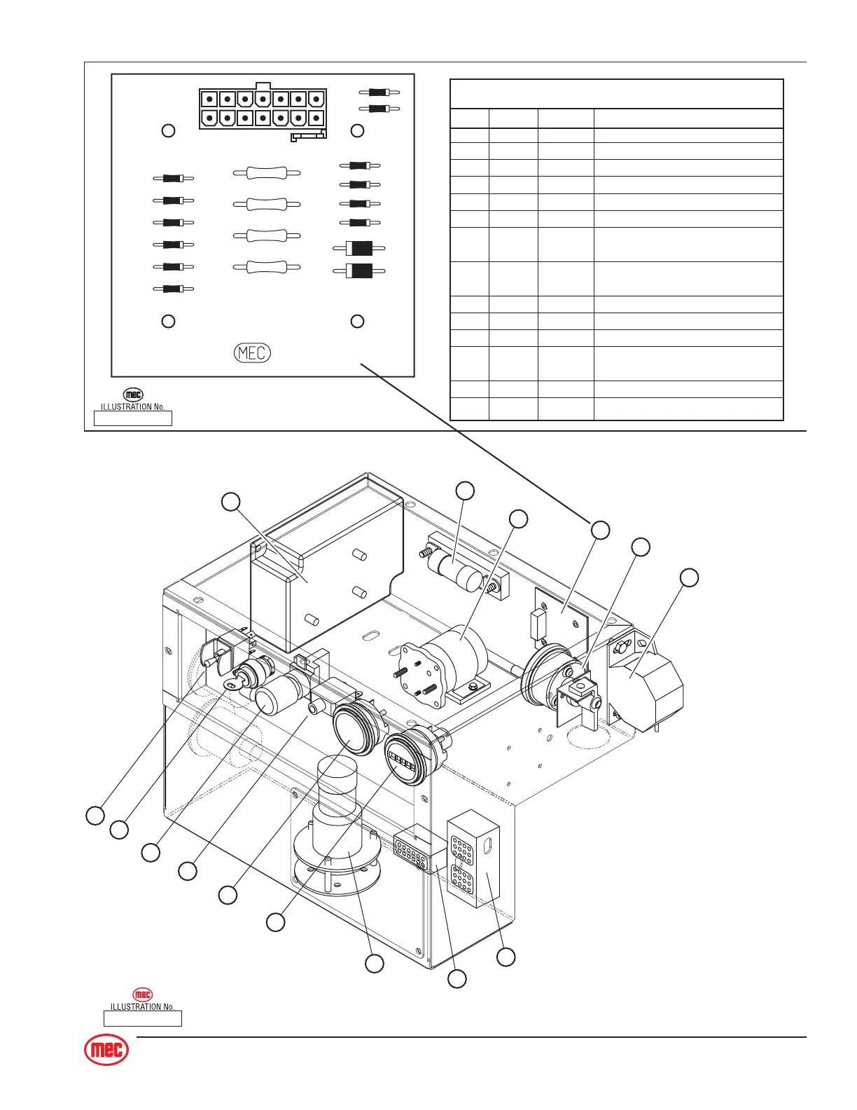
ART_2181
J1
14
71
8
D9
D10
D11
D15
TB1
D8
D7
D14
D5
D13
R2
R1
R3
R4
D3
D12
D4
D1
D2
8601
J1 Plug Pin Identification
PIN # WIRE # SIGNAL FUNCTION
1 10 INPUT Drive Reverse
2 11 INPUT Drive Forward
3 19 OUTPUT Brake, Decel Valve signal
4 8 INPUT Steer Left
5 18 OUTPUT Steer signal to Sevcon
6 5 INPUT Down signal
7 20 OUTPUT Signal to Motion Alarm(s)
(optional)
8 17 OUTPUT Sevcon & Hour Meter
(motor function requested)
9 15 INPUT Battery Negative
10 7 INPUT Steer Right
11 4 INPUT Lift Up
12 2 INPUT Limit Switch
(24V = platform down)
13 3 OUTPUT Enable, from lower Lift switch
14 21 OUTPUT To Sevcon (for speed cutback)
ART_2233
1] Fuse
2] Contactor
3] Tilt Sensor
4] Circuit (Diode) Board
5] MotorControl Unit
6] Main Harness Connection
7] Control Cable Connection
8] Motion Alarm (option)
9] Lift/Lower Switch
10] Platform-Base Selector
11] Emergency Stop Switch
13] Battery Gauge
14] Hour Meter
15] Battery Cutoff Switch
1
3
6
9
10
11
12
13
14
8
7
2
15
4
5