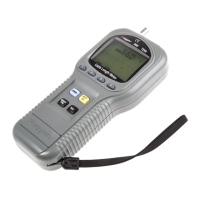
5.17.1 Test Success Header
5.17 Test Success
When a test completes successfully, the screen below
will be displayed.
The header contains useful information about the
test setup and how the ratio test was executed.
Information Description
From Test Setup
Found at top of header
Test ID
Vector Configuration
Primary Tap/Voltage
Secondary Tap/Voltage
From Test Setup
Found to the left of vector
From Test Setup
Found below Test ID
Displayed as both ASCII
text and vector
Test Mode
Test Voltage
From Test Setup
Test Voltage is voltage
applied phase to phase
TNR/TTR DisplayRatio
Display
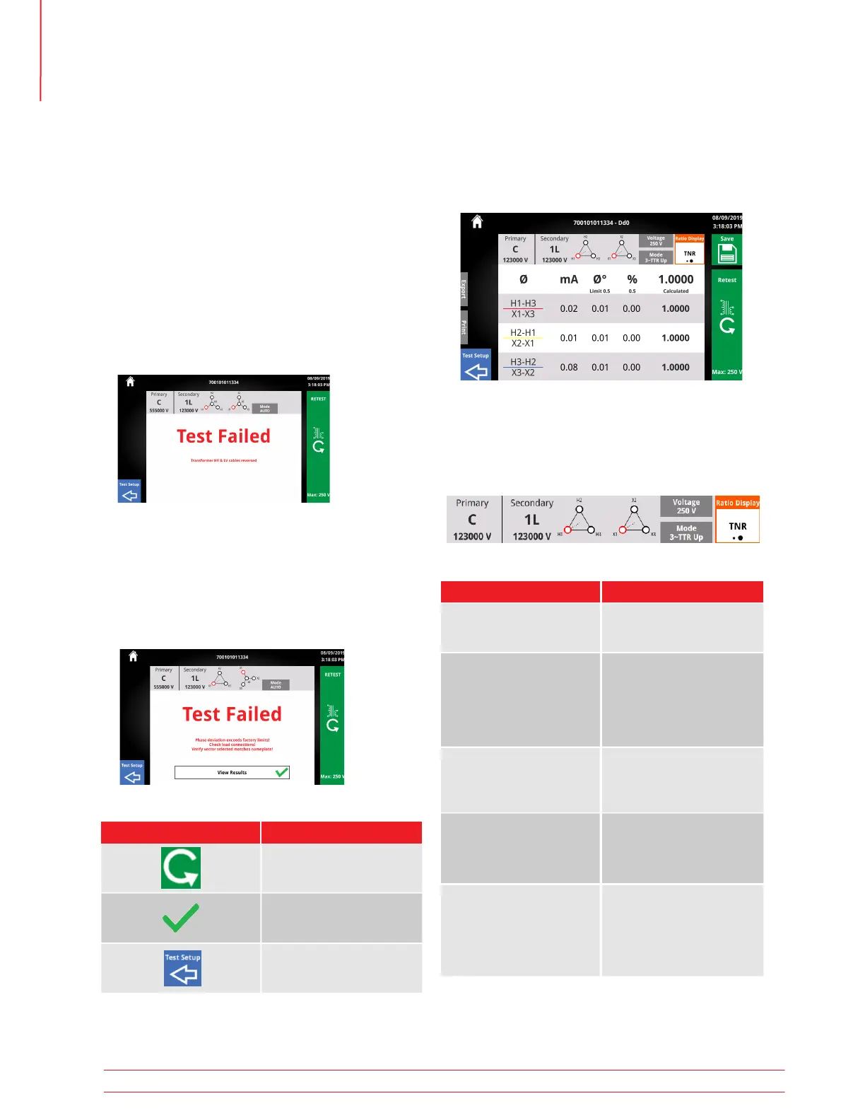
5.16 Test Failed
A test can fail for a number of reasons, including but
not limited to:
• Improper lead connections
• Improper vector selection
• Excessive current draw
If continuing a test is not possible due to safety
or connection issues, the Test Failed screen will be
displayed. Read the error message and the trouble-
shooting guide to determine the cause and resolu-
tion to the failure.
When using Auto mode, a test with failures will con-
tinue in 1Ø mode if no safety or connection issues
are present. A short circuit between leads is an ex-
ample of a failure that would allow a test to continue
in 1Ø mode.
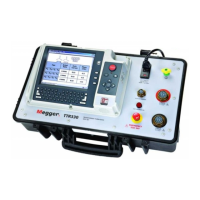
5.16.1 With Results
5.16.2 Test Failed Buttons
Button
Description
Retest
Return to Test Setup
View Results
Operation
32 TTRU3 User Manual us.megger.com