118
2: Adjust according to the current frequency
Set frequency
12.02%)10012.02(
3334
PfPfff ×=−×+=
The acceleration time means the time needed for the drive to accelerate from 0Hz to the maximum output
frequency (P02.15). The deceleration time means the time needed for the drive to decelerate from the
maximum output frequency (P02.15) to 0Hz.
Note
1.The time unit (min, s, 0.1s) of the acceleration/deceleration time 1~4 can be selected through P11.01 and
the default leave-factory unit is second.
2. For the drive of 22kW and below, the leave-factory value for its acceleration/deceleration time is 6.0s, for
the drive of 30~45kW, it is 20.0s, and for other modes of drives, it is 30.0s.
3. When it is used independently in case of no switch of motor 1, the first acceleration/deceleration time is
determined by P02.13 (acceleration time) and P02.14 (deceleration time). When it is used independently in
case of no switch of motor 2, the first acceleration/deceleration time is determined by P11.04 (acceleration
time) and P11.05 (deceleration time).
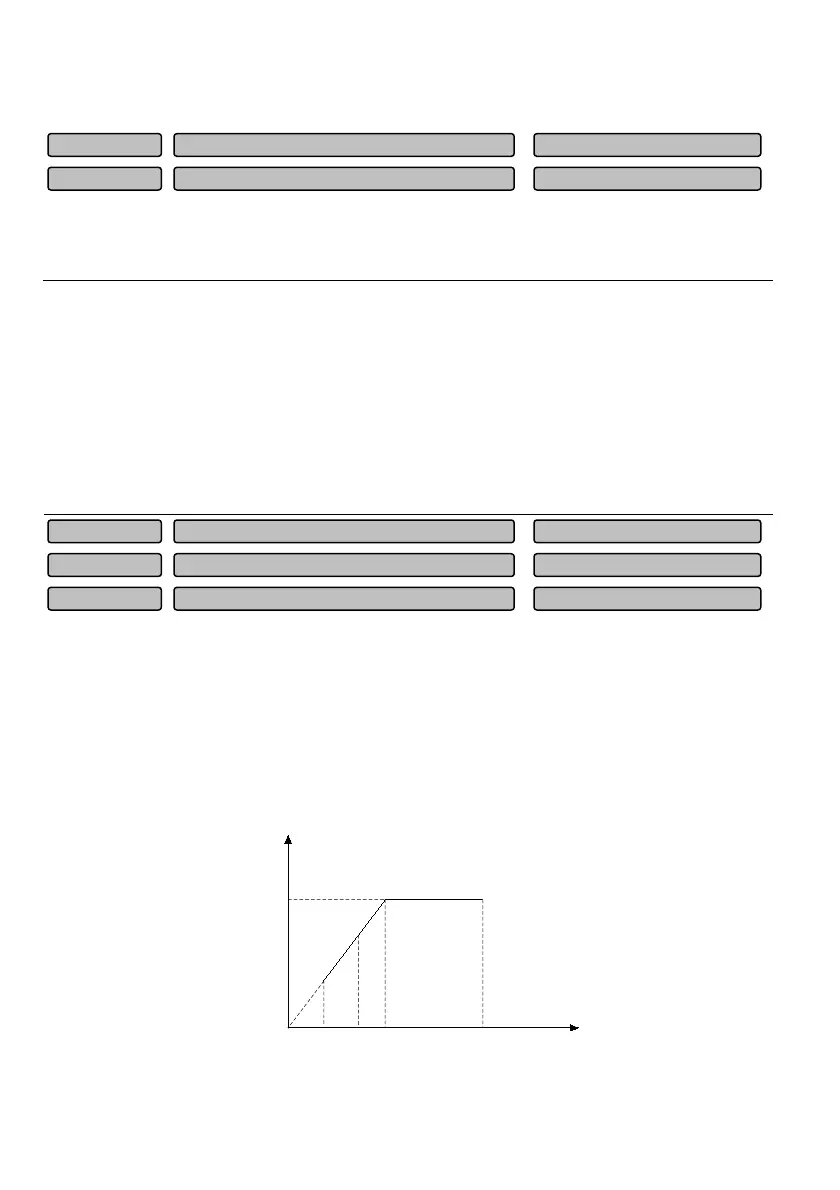
The maximum output frequency is the allowable maximum output frequency of the drive, as Fmax shown
in Fig. 6-8.
The upper limit frequency is the allowable maximum output running frequency set by the user, as FH
shown in Fig. 6-8.
The frequency of lower limit is the allowable minimum running frequency set by the user, as FL
shown in
Fig. 6-8.
F
b
in Fig. 6-8 is the basic running frequency, which is defined as the minimum value of corresponding
output frequency when the drive output voltage reaches the maximum value.
F
L
F
H
F
b
F
max
V
max
Output
voltage
Output
frequency
Fig.6-8 Diagram for the definition of limit frequency parameters
Maximum output frequency
max
50,P02.16
~3000.00
50.00
P02.15
Lower limit frequency
0.00~P02.16
0.00
P02.17
Upper limit frequency
P02.17~P02.15
50.00
P02.16
Deceleration time1
0.0~3600.0s
6.0s
P02.14
Acceleration time 1
0.0~3600.0s
6.0s
P02.13
 Loading...