29
4. “ ○ ” in the figure is main circuit terminal and “ ” in the figure is control circuit terminal.
5. For the usage of the control circuit terminal, please refer to section 3.2.
6. Fig. 3-3 is the wiring diagram for basic operation of model 75kWG/90kWP and below, and Fig. 3-4 is the
wiring diagram for basic operation of model 90kWG/110kWP and above, special attention should be paid to
these models: 355 kWP, 355 kWG, 400 kWP, 400 kWG, the main circuit terminal of external braking unit is P,
N.
3.2 Wiring and configuration of control circuit
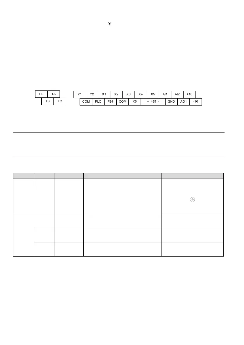
3.2.1 The arrangement sequence diagram of the control circuit terminals
Fig. 3-5 The arrangement sequence diagram of the control circuit terminals
3.2.2 Wiring of control circuit terminals
Note
It is suggested to use the wire with cross section area over 1mm
2
as the connecting wire of the control circuit
terminals.
For the terminal function description, please refer to Table 3-3.
Table 3-3 Table for the functions of interface board terminal
Type Terminal Name Function Specification
Shield PE
Shield
grounding
Used for the grounding of the shielded layer
of the wire. The shielded layer of the analog
signal wire, 485 communication wire and
motor power wire can be connected to this
terminal.
Connected to the main circuit
wiring terminal
internally
Power
supply
+10
+10V power
supply
To provide +10V reference power for
external load
Allowable maximum output
current: 10mA
-10
-10V power
supply
To provide -10V reference power for external
load
Allowable maximum output
current: 10mA
GND
+10V/-10V
power GND
The reference ground for analog signal and
+10V/-10V power
Internal isolated with COM
 Loading...